Steam exhaust cooling system of driving steam turbine of thermal power plant and thermal power unit

A technology for driving steam turbines and cooling systems, which is applied in steam engine installations, machines/engines, steam/steam condensers, etc., to achieve the effects of improving utilization, increasing cold air temperature, and low cost

Inactive Publication Date: 2014-02-12
CHINA POWER ENG CONSULTING GRP CORP EAST CHINA ELECTRIC POWER DESIGN INST
View PDF6 Cites 8 Cited by
  • Summary
  • Abstract
  • Description
  • Claims
  • Application Information

AI Technical Summary

Problems solved by technology

[0004] The exhaust steam cooling method of the existing drive steam turbine does not recover the energy in the exhaust steam regardless of wet cooling or air cooling

Method used


Image

  • Steam exhaust cooling system of driving steam turbine of thermal power plant and thermal power unit
  • Steam exhaust cooling system of driving steam turbine of thermal power plant and thermal power unit
  • Steam exhaust cooling system of driving steam turbine of thermal power plant and thermal power unit

Examples


Embodiment Construction

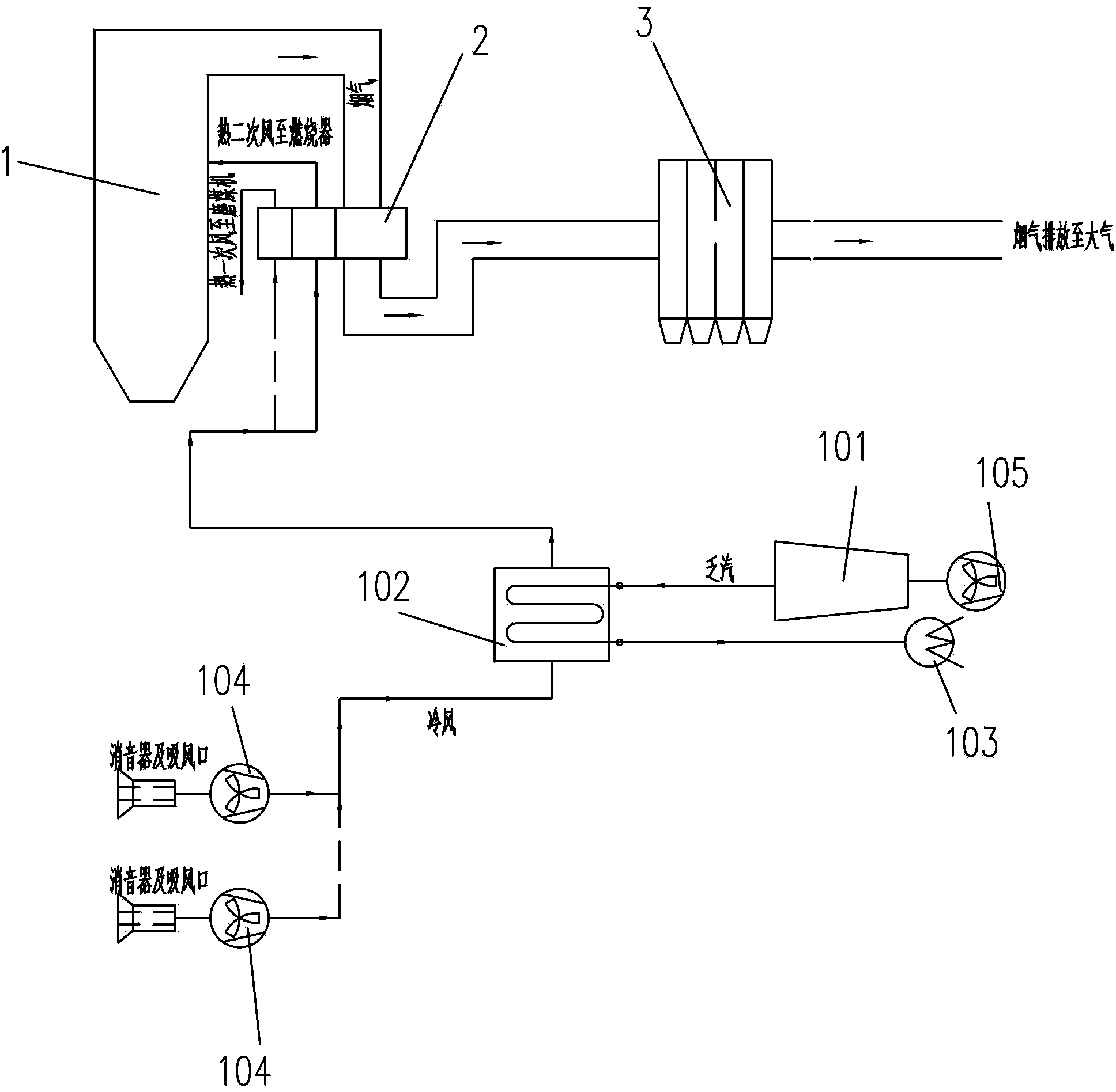
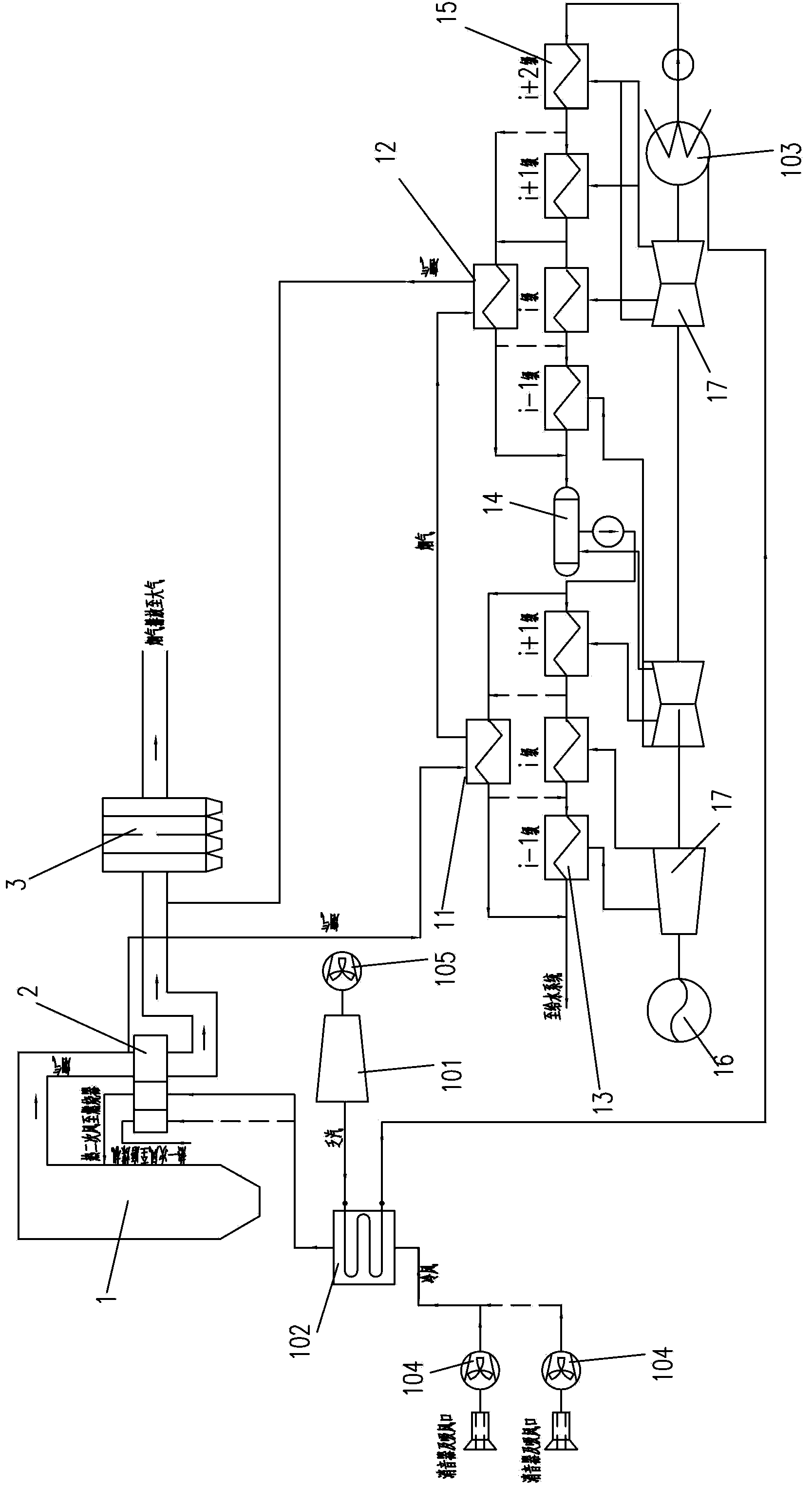
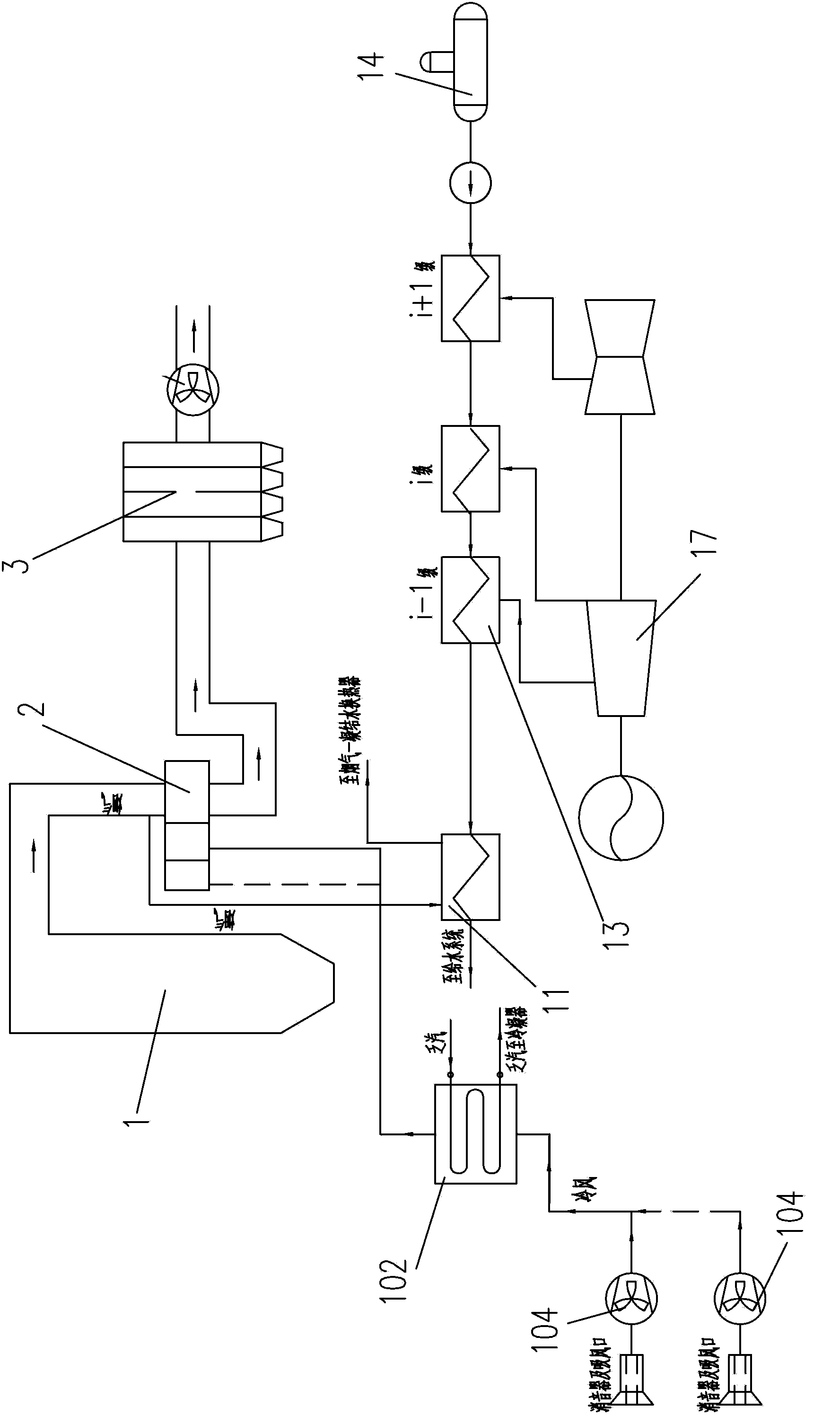
[0056] Preferred embodiments of the present invention will be described in detail below with reference to the accompanying drawings, so as to better understand the purpose, features and advantages of the present invention. It should be understood that the embodiments shown in the drawings are not intended to limit the scope of the present invention, but only to illustrate the essence of the technical solutions of the present invention. The same or similar parts in the figures are denoted by the same reference numerals.

[0057] Hereinafter, main technical terms of the present invention will be described.

[0058] Herein, the boiler mainly includes a boiler device. The boiler device is not specifically limited, as long as it does not limit the purpose of the present invention, it is known to those skilled in the art. It can use π-type boilers (or Pai-type boilers), tower boilers, inverted U-shaped boilers, etc., coal-fired boilers, oil-fired boilers, etc., natural circulation...


PUM


Abstract

The invention discloses a steam exhaust cooling system of a driving steam turbine of a thermal power plant and a thermal power unit. The steam exhaust cooling system of the driving steam turbine comprises the driving steam turbine, an air preheater and a fan and also comprises an air cooler; the steam exhaust of the driving steam turbine is cooled by the air cooler through the inlet air from the fan; the steam exhaust inlet of the air cooler is connected with the steam exhaust outlet of the driving steam turbine; the air inlet of the air cooler is connected with the fan; the air outlet of the air cooler is connected with the air inlet of the air preheater. According to the steam exhaust cooling system of the driving steam turbine of the thermal power plant and the thermal power unit, the steam exhaust energy of the driving steam turbine is effectively utilized and accordingly the efficiency of the thermal power plant is improved, meanwhile the coal consumption is reduced, and emissions of pollutants are reduced.

Description

technical field [0001] The invention relates to the field of thermal power generation, in particular to an exhaust steam cooling system for driving a steam turbine in thermal power generation. Background technique [0002] With the development of the national economy, the society's demand for electricity is constantly increasing. For emerging developing countries that are undergoing industrialization and rapid economic development, such as China, the consumption of electricity and the installed capacity of power plants are increasing rapidly. As far as China is concerned, due to the limitation of its primary energy storage types and storage capacity, coal has been the main fuel for power plants in recent decades, accounting for more than 70%, and this trend will not occur in the foreseeable future. radical change. Although coal-fired power plants have advantages such as low cost and wide range of fuel sources for China, they have disadvantages such as low efficiency and hi...

Claims


Application Information

Patent Timeline
IPC IPC(8): F28B1/06F23L15/00F22D1/36F22D11/06F01K17/02F01D15/08F01D15/10
CPCY02E20/34
Inventor 申松林叶勇健陈仁杰施刚夜
Owner CHINA POWER ENG CONSULTING GRP CORP EAST CHINA ELECTRIC POWER DESIGN INST
Why Eureka
Try Eureka