
Manufacturing method of surface mount coil inductor

A coil inductance, surface mount technology, applied in the direction of inductance/transformer/magnet manufacturing, inductors, fixed inductors, etc., can solve the problems of unstable electrical connection performance of coil inductance, complicated manufacturing process, increased manufacturing cost, etc., to achieve Reduced manufacturing steps, simple manufacturing process, and low manufacturing cost

Active Publication Date: 2014-02-12
SHIN YUAN ELECTRONICS PROD KUNSHAN
View PDF5 Cites 2 Cited by
  • Summary
  • Abstract
  • Description
  • Claims
  • Application Information

AI Technical Summary

Problems solved by technology

[0009] The manufacturing method of the above coil inductance, because its structure includes a coil, a terminal piece, and a packaging case, must include the steps of making the terminal piece during production, and also weld the terminal wires of the coil and the terminal piece. The process is more complicated
In addition, when the terminal wire of the coil is welded to the metal sheet, the welding point is prone to false welding and false welding, so that the electrical connection performance of the packaged coil inductor is unstable.
In addition, in the manufacturing method of the above-mentioned coil inductor, since the terminal piece is welded on the terminal wire of the coil, therefore, its manufacturing cost is increased.

Method used


Image

  • Manufacturing method of surface mount coil inductor
  • Manufacturing method of surface mount coil inductor
  • Manufacturing method of surface mount coil inductor

Examples


Embodiment 1

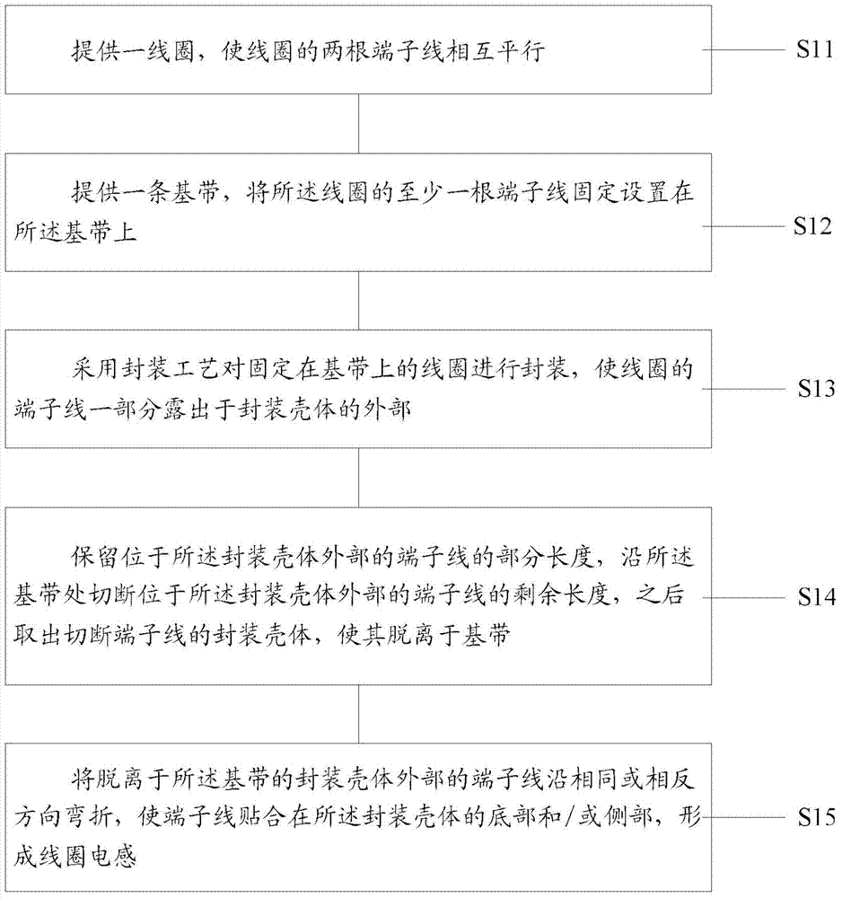
[0050] Please refer to figure 1 , 1A To 11, the manufacturing method of the surface mount coil inductance of the present embodiment 1 comprises the following steps:

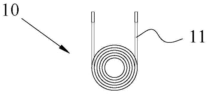
[0051] Step S11, please refer to Figure 1A , providing a coil 10 so that the two terminal wires 11 of the coil 10 are parallel to each other;

[0052] Step S12, please refer to Figures 1B to 1C , providing a base band 20, and fixing at least one terminal wire 11 of the coil 10 on the base band 20;

[0053] Step S13, please refer to Figure 1D , using a packaging process to package the coil 10 fixed on the base tape 20, so that a part of the terminal wire 11 of the coil 10 is exposed outside the package casing 30;

[0054] Step S14, please refer to Figure 1D , 1E, reserving a part of the length of the terminal wire 11 located outside the packaging case 30, cutting off the remaining length of the terminal wire 11 located outside the packaging case 30 along the base tape 20, and then taking out the termina...

Embodiment 2

[0061] Please refer to figure 2 , 2A Up to 2J, the manufacturing method of the surface mount coil inductor of the second embodiment is basically the same as that of the first embodiment, both of which are made by using the baseband 20 to fix the terminal wire 11 of the coil 10, including the following steps:

[0062] Step S21, please refer to Figures 2A to 2B , providing a coil 10, expanding each terminal wire 11 of the coil 10 so that the two terminal wires 11 are parallel to each other or located on the same center line;

[0063] Step S22, please refer to Figures 2C to 2D , please provide two base strips 20 parallel to each other, and fix at least one terminal wire 11 of the coil 10 on at least one of the base strips 20;

[0064] Step S23, please refer to Figure 2E , using a packaging process to package the coil 10, so that a part of each terminal wire 11 of the coil 10 is exposed outside the package casing 30;

[0065] Step S24, please refer to Figure 2F , keep p...


PUM


Abstract

The invention discloses a manufacturing method of a surface mount coil inductor. The manufacturing method comprises the following steps of: providing a coil and a baseband, and fixing at least one terminal wire of the coil on the baseband; encapsulating the coil by an encapsulation process, so that the terminal wires of the coil are exposed to the outside of an encapsulation shell; reserving the partial length of the terminal wire outside the encapsulation shell, cutting off the remaining length of the terminal wire outside the encapsulation shell, and taking out the encapsulation shell outside which the terminal wire is cut off, so that the encapsulation shell is separated from the baseband; bending the wire terminal outside the encapsulation shell separated from the baseband in the same or opposite direction, so that the terminal wire is bonded to the bottom and / or the side of the encapsulation shell to form a coil inductor. The manufacturing method provided by the invention has the advantages of stable electrical connection performance, simple manufacturing process, low manufacturing cost and the like.

Description

technical field [0001] The invention relates to a method for manufacturing a surface mounted coil inductance. Background technique [0002] Coil inductance is divided into plug-in coil inductance and surface mount coil inductance. Among them, surface mount inductors, also known as patch coil inductors, generally include a coil with a certain inductance, a package shell, and a terminal piece made of metal material connected to the two terminal wires at both ends of the coil. The inside of the packaging case, a part of the terminal strip is located inside the packaging case, and the other part is located outside the packaging case and exposed outside the packaging case. The coil inductor with the above structure includes a coil, a terminal piece, and a packaging shell, which makes the structure complex. The above-mentioned terminal piece exposed outside the package shell is used as the pin of the surface mount coil inductor. Since the terminal piece is flat, the pin of the c...

Claims


Application Information

Patent Timeline
IPC IPC(8): H01F41/00H01F37/00
Inventor 钟宗原
Owner SHIN YUAN ELECTRONICS PROD KUNSHAN
Learn More