Centrifugal pump shaft seal water cooling heat dissipation protection system

A water-cooled heat dissipation and protection system technology, applied in the field of centrifugal pumps, can solve the problems of incomplete, untimely cooling, and difficult to reach, and achieve the effects of reasonable structure design, extended service life, and smooth and normal operation.

Active Publication Date: 2016-05-11
七台河宝泰隆新能源有限公司
View PDF10 Cites 0 Cited by
  • Summary
  • Abstract
  • Description
  • Claims
  • Application Information

AI Technical Summary

Problems solved by technology

For example, when the shaft seal is cooled, there are often problems such as untimely and incomplete cooling, poor selection of cooling positions, etc.
If the cooling effect is not good, it is easy to damage the friction pair between the dynamic and static rings of the mechanical seal, thereby destroying the mechanical seal and causing the pump to fail to work normally.
Especially when cooling water is supplied, there is no valve to control the flow, and it is difficult to ensure sufficient supply of cooling water in the end branch. If the water level is slightly higher, the cooling water will be more difficult to reach, which will affect the cooling effect of the shaft seal.

Method used


Image

  • Centrifugal pump shaft seal water cooling heat dissipation protection system
  • Centrifugal pump shaft seal water cooling heat dissipation protection system

Examples


Embodiment 1

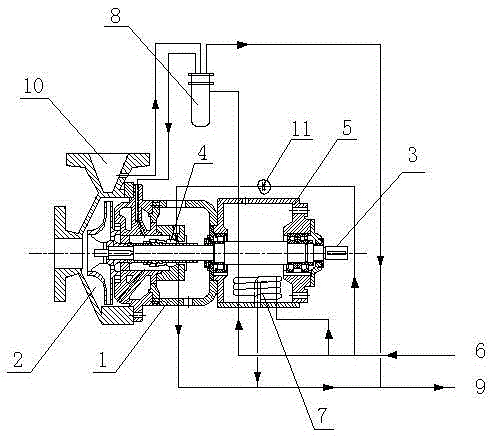
[0011] The centrifugal pump shaft seal water cooling and heat dissipation protection system of the present invention includes a pump casing 1, an impeller casing chamber 2, a pump shaft 3, a shaft seal 4 and a bearing housing 5, and the cooling water line 6 is respectively connected to the inlet of the coil pipe 7 in the bearing housing, The inlet of the outer chamber of the shaft seal 4 and the inlet of the shell side of the heat exchanger 8 are connected; the cooling water return line 9 is respectively connected with the outlet of the coil 7, the outlet of the outer chamber of the shaft seal 4, and the outlet of the shell side of the heat exchanger 8 .

Embodiment 2

[0013] The centrifugal pump shaft seal water cooling and heat dissipation protection system of the present invention includes a pump casing 1, an impeller casing chamber 2, a pump shaft 3, a shaft seal 4 and a bearing housing 5, and the cooling water line 6 is respectively connected to the inlet of the coil pipe 7 in the bearing housing, The inlet of the outer chamber of the shaft seal 4 and the inlet of the shell side of the heat exchanger 8 are connected; the cooling water return line 9 is respectively connected with the outlet of the coil 7, the outlet of the outer chamber of the shaft seal 4, and the outlet of the shell side of the heat exchanger 8 . The outlet of the tube side of the heat exchanger 8 is connected to the inlet of the inner end chamber of the shaft seal 4 in the pump casing 1, and the inner end chamber outlet of the shaft seal 4 passes through the impeller housing chamber 2 to the pump outlet 10 and the tube side of the heat exchanger 8 The entrance is conn...

Embodiment 3

[0015] The centrifugal pump shaft seal water cooling and heat dissipation protection system of the present invention includes a pump casing 1, an impeller casing chamber 2, a pump shaft 3, a shaft seal 4 and a bearing housing 5, and the cooling water line 6 is respectively connected to the inlet of the coil pipe 7 in the bearing housing, The inlet of the outer chamber of the shaft seal 4 and the inlet of the shell side of the heat exchanger 8 are connected; the cooling water return line 9 is respectively connected with the outlet of the coil 7, the outlet of the outer chamber of the shaft seal 4, and the outlet of the shell side of the heat exchanger 8 . The outlet of the tube side of the heat exchanger 8 is connected to the inlet of the inner end chamber of the shaft seal 4 in the pump casing 1, and the inner end chamber outlet of the shaft seal 4 passes through the impeller housing chamber 2 to the pump outlet 10 and the tube side of the heat exchanger 8 The entrance is conn...


PUM


Abstract

The invention relates to the technical field of centrifugal pumps, in particular to a centrifugal pump shaft seal water-cooling and heat dissipation protection system, which includes a pump casing, an impeller casing chamber, a pump shaft, a shaft seal and a bearing box, and the cooling upper water lines are respectively separated from the coil pipes in the bearing box The inlet, the chamber inlet at the outer end of the shaft seal, and the shell side inlet of the heat exchanger are connected; the cooling water return line is respectively connected with the coil outlet, the chamber outlet at the outer end of the shaft seal, and the shell side outlet of the heat exchanger. The invention has reasonable structure and simple operation. In actual application, the invention can effectively dissipate heat for the shaft seal, prolong the service life of the mechanical seal of this type of pump, reduce the number of maintenance of the pump, make the cooling water branch at the end abundant, and bring about smooth operation of the system. Assure.

Description

technical field [0001] The invention relates to the technical field of centrifugal pumps, in particular to a centrifugal pump shaft seal water cooling and heat dissipation protection system. Background technique [0002] Centrifugal pumps work by using the centrifugal force generated by the water caused by the rotation of the impeller. Before starting the pump, the pump casing and the suction pipe must be filled with water, and then the motor is started to drive the impeller and the water to rotate at a high speed. The flow channel flows into the pressure water pipeline of the water pump. At present, the utilization rate of centrifugal pumps in production is extremely high, but when they are actually used in factories, some problems often occur. For example, when the shaft seal is cooled, there are often problems such as untimely and incomplete cooling, and poor selection of cooling locations. If the cooling effect is not good, it is easy to damage the friction pair betwe...

Claims


Application Information

Patent Timeline
Patent Type & Authority Patents(China)
IPC IPC(8): F04D29/58F04D29/10
Inventor 宫振宇肖楠
Owner 七台河宝泰隆新能源有限公司
Why Eureka
Try Eureka