Method and device for testing digital array module transmitting channel phase congruency

A technology of digital array and transmission channel, which is applied in the direction of measuring device, phase angle between voltage and current, measuring electrical variables, etc. It can solve the problems that the internal synchronization mode cannot be used, and the digital array module has no synchronization signal input/output, etc. Achieve the effects of high test efficiency, high test accuracy, and optimized transmission path

Active Publication Date: 2014-02-19
CHINA ELECTRONIS TECH INSTR CO LTD
View PDF4 Cites 15 Cited by
  • Summary
  • Abstract
  • Description
  • Claims
  • Application Information

AI Technical Summary

Problems solved by technology

[0008] 3) The digital array module itself has no synchronous signal input / output
[0010] Different from traditional analog T / R components, since the digital array module transmit channel does not input the analog RF excitation signal, it cannot be tested by the transmission mode of the pulse vector network analyzer.
In addition, the output signal of the transmission channel of the digital array module is a complex modulation signal in the pulse, so it is necessary to ensure that the transmission signal and the pulse vector network analyzer establish a synchronous relationship during the test, but because the digital array module does not require the input of the pulse vector network analyzer stimulus signal, the internal synchronization mode used in the simulation of T / R component testing cannot be used
To sum up, the test method used by analog T / R to directly use the transmission mode of pulse vector analyzer to realize the phase consistency of the transmission channel is no longer suitable for digital T / R components

Method used


Image

  • Method and device for testing digital array module transmitting channel phase congruency

Examples


Embodiment Construction

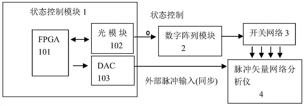
[0033] combine figure 1 , a digital array module transmit channel phase consistency test method, comprising the steps of:

[0034] a Establish a state control module 1 , the state control module includes FPGA101 , optical module 102 and DAC chip 103 . First, the FPGA is connected to the digital array module 2 through the optical module, and the digital array module is connected to the pulse vector network analyzer 4 through the switch network 3; the second is connected to the external synchronous pulse input port of the pulse vector network analyzer through the DAC.

[0035]b On the rising edge of the clock signal, the state control module controls the working state of the digital array module through the optical module, and at the same time transmits the synchronization signal data to the DAC chip in the state control module, so that the state control module outputs one channel and the working state of the digital array module The synchronous pulse signal uses the pulse sign...


PUM


Abstract

The invention discloses a method and device for testing digital array module transmitting channel phase congruency. The method includes the following steps that a state control module based on an FPGA is established; on the rising edge of a clock signal, the state control module controls the operating state of a digital array module through an optical module, meanwhile the state control module is made to output a pulse signal which is synchronous with the operating state of the digital array module, and the synchronous relation between the digital array module and a pulse vector network analyzer is established with the synchronous signals as the link; under switching of a switching network, a plurality of transmitting signals are simultaneously input into a receiver channel of the pulse vector network analyzer, and transmitting channel phase congruency indexes are obtained through normalization computing and phase difference computing. According to the method, digital array module transmitting channel phase congruency testing is achieved through establishment of a synchronization mechanism and introduction of multi-channel coherence tests; meanwhile, the transmission path of transmitting signals is optimized, insertion losses of the channel are reduced, and impedance matching is improved.

Description

technical field [0001] The invention relates to a method for testing the phase consistency of the transmission channel of a digital array module and a device for testing the phase consistency of the transmission channel of the digital array module. Background technique [0002] Digital array radar is a fully digital phased array radar that adopts digital beamforming technology for both transmission and reception. Compared with traditional phased array radar, digital array radar has its incomparable advantages, such as large dynamic range, easy realization of multi-beam, low loss, low sidelobe, low angle measurement with high precision, strong manufacturability, and reliable system tasks High sex. Therefore, the application prospect of digital array radar is very broad. The digital array module is the most important and most numerous basic unit of the digital array radar. [0003] The digital array module is a microwave-digital mixed multi-channel radar transmitting / receiv...

Claims


Application Information

Patent Timeline
IPC IPC(8): G01S7/40
CPCG01R25/005G01S7/4008
Inventor 丁志钊吴家亮张龙蒋玉峰
Owner CHINA ELECTRONIS TECH INSTR CO LTD
Why Eureka
Try Eureka