Method of directly manufacturing antenna on soft magnetic ferrite

A soft ferrite and antenna technology, applied in the direction of antenna coupling, antenna support/installation device, radiating element structure, etc. Effect

Inactive Publication Date: 2014-02-19
SHANGHAI DEMAN ELECTRONICS TECH
View PDF3 Cites 5 Cited by
  • Summary
  • Abstract
  • Description
  • Claims
  • Application Information

AI Technical Summary

Problems solved by technology

The first three lows are its shortcomings, which limit its scope of use, and are now working hard to improve

Method used


Image

  • Method of directly manufacturing antenna on soft magnetic ferrite
  • Method of directly manufacturing antenna on soft magnetic ferrite
  • Method of directly manufacturing antenna on soft magnetic ferrite

Examples


Embodiment 1

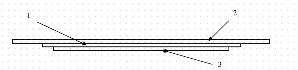
[0035] like figure 1 Shown, a kind of method directly manufacturing antenna on soft ferrite, this method comprises the following steps:

[0036] (1) Paste the protective layer 2, that is, PET film, on the upper surface of the soft ferrite layer 1, and print ink to enhance adhesion on the lower surface according to the antenna pattern, and then dry it at 200°C;

[0037] (2) Then print the conductive ink 3 on the ink that enhances the adhesion, and dry it at 150°C;

[0038] (3) Apply superglue under the conductive ink and attach the peel-off layer.

[0039] During use, the peeling layer is torn off, and the soft ferrite provided with the antenna is pasted on the plastic case of the mobile phone to be installed with the antenna, so that the soft ferrite layer 1 is located between the antenna and the electromagnetic wave generation source.

[0040] The strong printing ink (being Primer printing ink) that adopts in the above-mentioned steps comprises the component of following we...

Embodiment 2

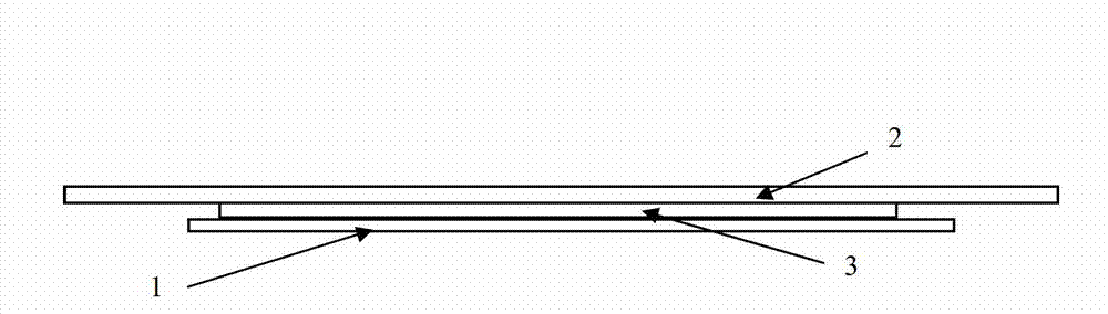
[0042] like figure 2 Shown, a kind of method directly manufacturing antenna on soft ferrite, this method comprises the following steps:

[0043] (1) Printing ink to enhance adhesion on the upper surface of the soft ferrite layer 1 according to the antenna pattern, and then drying at 180° C.;

[0044] (2) Then print the conductive ink 3 on the ink that enhances the adhesion, and dry it at 120° C. to form an antenna;

[0045] (3) Protective layer 2, namely the protective film of PP material, is set above the conductive ink;

[0046] (4) Apply superglue on the lower surface of the soft ferrite layer 1 and attach a peeling layer.

[0047] During use, the peeling layer is torn off, and the soft magnetic ferrite provided with the antenna is pasted on the plastic case of the mobile phone to be installed with the antenna, so that the soft ferrite layer 1 is located between the antenna and the electromagnetic wave generation source.

[0048] The strong printing ink (being Primer prin...

Embodiment 3

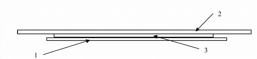
[0050] like image 3 Shown, a kind of method directly manufacturing antenna on soft ferrite, this method comprises the following steps:

[0051] (1) Print the ink to enhance adhesion on the lower surface of the protective layer 2 according to the antenna pattern, and then dry it at 60°C;

[0052] (2) Then print the conductive ink 3 on the ink that enhances the adhesion, and dry it at 60° C. to form an antenna;

[0053] (3) setting a soft ferrite layer 1 under the conductive ink;

[0054] (4) Apply superglue on the lower surface of the soft ferrite layer 1 and attach a peeling layer.

[0055] During use, the peeling layer is torn off, and the soft ferrite provided with the antenna is pasted on the plastic case of the mobile phone to be installed with the antenna, so that the soft ferrite layer 1 is located between the antenna and the electromagnetic wave generation source.

[0056] The strong ink (i.e. Primer ink) of the adhesive strength that adopts in the above steps compr...


PUM


Abstract

The invention relates to a method of directly manufacturing an antenna on a soft magnetic ferrite. The method is characterized in that the antenna is directly arranged on the soft magnetic ferrite; the soft magnetic ferrite which is provided with the antenna is pasted on an electronic component to be equipped with the antenna; the soft magnetic ferrite is used to absorb an electromagnetic wave. Compared to the prior art, by using the method of the invention, there are the following advantages that through using a characteristic of electromagnetic wave absorption of the soft magnetic ferrite, antenna performance is increased; the thickness of the antenna is reduced so that the thickness of a product is reduced too. Simultaneously, the surface of the soft magnetic ferrite is flat and soft; mass production of the antenna can be realized and the method is not limited by an installation position.

Description

technical field [0001] The invention relates to an antenna, in particular to a method for directly manufacturing the antenna on soft magnetic ferrite. Background technique [0002] Antennas of electronic components are gradually shifting from external antennas to built-in antennas. The built-in antenna is to set the antenna on the surface of the plastic shell inside the electronic component (such as a mobile phone). In the past, mobile phone antennas only needed to meet the call function, but with the diversification of mobile phone performance, the antenna performance is also required to be diversified. Such as NFC antenna for mobile phone payment, GPS antenna for location tracker and other functions are gathering. Moreover, like the performance of the antenna, the electronic component circuit must also have a lot of performance, the consumption of the battery will increase, and the electromagnetic waves emitted from the battery will inevitably increase. Electromagnetic w...

Claims


Application Information

Patent Timeline
Patent Type & Authority Applications(China)
IPC IPC(8): H01Q1/22H01Q1/52H01Q1/38
Inventor 杨流国戢树修
Owner SHANGHAI DEMAN ELECTRONICS TECH
Why Eureka
Try Eureka