Continuous-casting crystallizer vibration simulation test unit and non-sine vibration control method thereof

A technology of continuous casting mold and simulation test, applied in the field of continuous casting mold simulation application of iron and steel metallurgy, can solve the problems of unfavorable technical level, high operation and maintenance, expensive investment, etc., and achieves a simple and clear speed curve, strong adaptability, Easy-to-get effects

Inactive Publication Date: 2014-02-26
NORTHEASTERN UNIV
View PDF5 Cites 13 Cited by
  • Summary
  • Abstract
  • Description
  • Claims
  • Application Information

AI Technical Summary

Problems solved by technology

Whether the vibration device of the continuous casting machine is mechanical or hydraulic, it is not conducive to the simulation test research due to the complex system, expensive investment, and high technical level of operation and maintenance. A continuous casting mold with simple operation and flexible adjustment is proposed The non-sinusoidal vibration waveform control method of the vibration simulation test device is particularly critical

Method used


Image

  • Continuous-casting crystallizer vibration simulation test unit and non-sine vibration control method thereof
  • Continuous-casting crystallizer vibration simulation test unit and non-sine vibration control method thereof
  • Continuous-casting crystallizer vibration simulation test unit and non-sine vibration control method thereof

Examples


Embodiment Construction

[0026] The specific implementation manners of the present invention will be described in detail below in conjunction with the accompanying drawings.

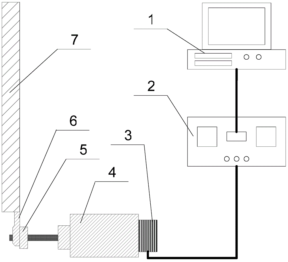
[0027] like figure 1 As shown, a continuous casting crystallizer vibration simulation test device includes a main control computer 1, a controller 2, a motor driver 3, a stepping motor 4, an eccentric wheel 5, a connecting rod 6 and a device for simulating a continuous casting mold copper plate Vibration plate 7;

[0028] The main control computer 1 is connected to the input end of the controller 2, the output end of the controller 2 is connected to the input end of the motor driver 3, the output end of the motor driver 3 is connected to the control input end of the stepping motor 4, and the output shaft of the stepping motor 4 is connected to An eccentric wheel 5, one side of the eccentric wheel 5 is connected to one end of the connecting rod 6, and the vibrating plate 7 is vertically connected to the other end of the connecti...


PUM


Abstract

The invention provides a continuous-casting crystallizer vibration simulation test unit and a non-sine vibration control method of the continuous-casting crystallizer vibration simulation test unit, and belongs to the technical field of ferrous metallurgy continuous-casting crystallizer simulation application. The continuous-casting crystallizer vibration simulation test unit comprises a main control computer, a controller, a motor driver, a stepping motor, an eccentric wheel, a connecting rod and a vibrating plate used for simulating a continuous-casting crystallizer copper plate. The non-sine vibration control method of the continuous-casting crystallizer vibration simulation test unit comprises the following steps: vibration speeds of the vibrating plate at all moments in the non-sine vibration process are set; the set vibration speeds of the vibrating plate at all the moments are converted into vertical velocity components of the eccentric wheel at all the moments, so that rotation speeds of the eccentric wheel at all the moments are obtained; rotation speeds of the stepping motor at all the moments are obtained, and the controller controls the stepping motor to rotate at the rotation speeds at all the moments through the motor driver; the stepping motor drives the eccentric wheel to rotate in real time and then drives the vibrating plate to conduct non-sine vibration. According to the continuous-casting crystallizer vibration simulation test unit and the non-sine vibration control method of the continuous-casting crystallizer vibration simulation test unit, a mechanical drive mode is adopted for realizing non-sine vibration, a piecewise function method is adopted for establishing a velocity curve, and therefore vibration technological parameters are easy to acquire.

Description

technical field [0001] The invention belongs to the technical field of iron and steel metallurgy continuous casting mold simulation application, and in particular relates to a continuous casting mold vibration simulation test device and a non-sinusoidal vibration control method thereof. Background technique [0002] Continuous casting plays an important role in the manufacturing process of steel products as a link between the preceding and the following. The mold, known as the "heart of the continuous casting machine", has important functions such as efficient heat transfer, solidification and forming, purification of molten steel, and quality control. As an important feature of continuous casting technology, mold vibration is effectively used to reduce the friction between the mold and the slab, prevent the slab shell from sticking to the wall of the mold, make the slab demould smoothly, and obtain a good surface quality of the slab . In addition, vibration can also heal t...

Claims


Application Information

Patent Timeline
IPC IPC(8): B22D11/053B22D11/16
Inventor 孟祥宁杨杰朱苗勇
Owner NORTHEASTERN UNIV
Why Eureka
Try Eureka