Micro-displacement Optical Lever Laser Measurement System and Its Magnetomechanical Oxygen Sensor

A technology of laser measurement system and optical lever, which is applied in the laser measurement system and its application field, can solve the problems of affecting the measurement effect, poor mechanical strength, large beam divergence, etc., so as to avoid the process of adjusting the optical focus, save the cost of use, and ensure the accuracy sexual effect

Active Publication Date: 2016-04-13
CHONGQING CHUANYI ANALYZER CO LTD
View PDF6 Cites 0 Cited by
  • Summary
  • Abstract
  • Description
  • Claims
  • Application Information

AI Technical Summary

Problems solved by technology

When using white light, due to the large divergence of the beam, in order to avoid affecting the measurement effect, it is necessary to configure a lens collimator to change the divergent beam into a parallel beam. The optical focus needs to be adjusted, which increases the complexity of the measurement
When using a laser lamp, due to the strong directional light emitting characteristics of the laser, generally no collimation device is required, but when using a laser diode to emit laser light, there is inevitably a certain emission angle. If the collimation device is not configured, the laser beam will still There is divergence, which affects the measurement effect

Method used


Image

  • Micro-displacement Optical Lever Laser Measurement System and Its Magnetomechanical Oxygen Sensor
  • Micro-displacement Optical Lever Laser Measurement System and Its Magnetomechanical Oxygen Sensor
  • Micro-displacement Optical Lever Laser Measurement System and Its Magnetomechanical Oxygen Sensor

Examples


Embodiment Construction

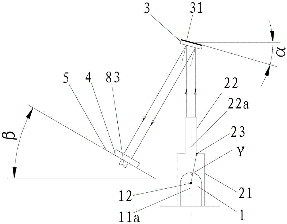
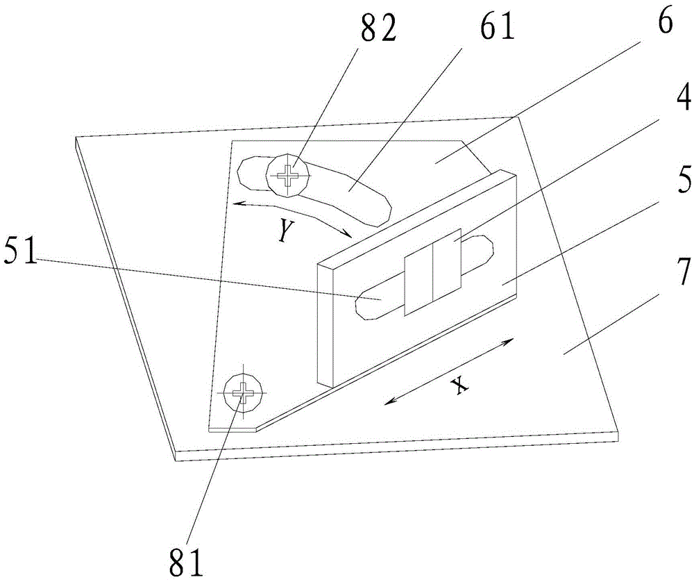
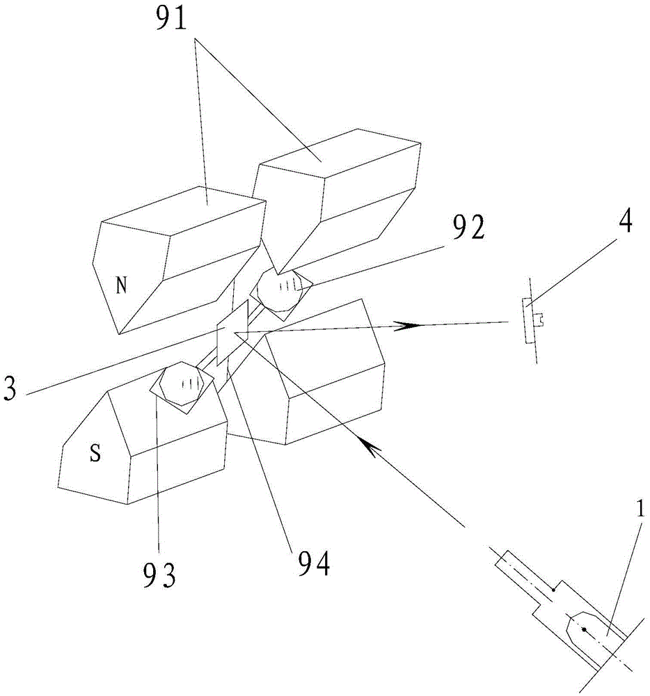
[0021] figure 1 It is a structural schematic diagram of the micro-displacement optical lever laser measurement system of the present invention, figure 2 It is a structural schematic diagram of the photoelectric detector and the mounting assembly of the present invention, image 3 It is a schematic structural diagram of the magnetomechanical oxygen sensor of the present invention, as shown in the figure: the micro-displacement optical lever laser measurement system of this embodiment includes: a laser generator for emitting laser beams; a beam collimator for collimating Straighten the laser beam emitted by the laser generator; the plane mirror 3 is used to reflect the laser beam collimated by the beam collimator; and the photodetector 4 is used to receive the laser beam reflected by the plane mirror 3 Beam and output electrical signal; wherein, the laser generator includes a laser diode 1, the beam collimator includes a bottom tube 21 for covering the transparent package of t...


PUM

PropertyMeasurementUnit
lengthaaaaaaaaaa

Abstract

The invention discloses a micro-displacement optical lever laser measurement system and a magnetic mechanical oxygen sensor of the micro-displacement optical lever laser measurement system. The micro-displacement optical lever laser measurement system comprises a laser generator, a light beam collimator, a plane mirror and a photoelectric detector, wherein the laser generator comprises a laser diode, the light beam collimator comprises a transparent packaging bottom tube used for covering the laser diode, the bottom tube protrudes upward to form a collimator tube with a vertical hole channel, and the axis of the collimator tube and the axis of the transparent packaging bottom tube are on the same straight line. The collimator tube is aligned with the central part of the emitting face of the laser diode, and the light intensity and the travel path of the part of light will not be changed; the rest of the light is radiated onto the inner wall of the bottom tube or the inner wall of the collimator tube at a certain angle and is reflected many time on the inner wall, the light intensity of the rest of the light is attenuated along with increasing of the number of times of reflection and meanwhile is attenuated along with increasing of the optical path, the rest of the light has faded away before reaching the plane mirror, the linear light beam of the central part is retained, and thus the collimation purpose is achieved.

Description

technical field [0001] The invention relates to a laser measurement system and its application, in particular to a micro-displacement optical lever laser measurement system and a magnetomechanical oxygen sensor. Background technique [0002] Micro-displacement measurement In measurement technology, various physical quantities such as vibration, rotation angle, pressure, strain, acceleration and flow can be measured by detecting displacement. All gases exhibit paramagnetism or diamagnetism in a magnetic field, and oxygen has a strong paramagnetism. Other gases except NO and NO 2 In addition, it shows very weak paramagnetism or diamagnetism. Using this characteristic of oxygen, the concentration of oxygen can be measured with a magnetomechanical structure. The sensor using this principle is called a magnetomechanical oxygen sensor. The existing magnetomechanical oxygen sensor consists of a measuring cell with two strong magnetic poles, a suspension spring, a dumbbell-shaped m...

Claims


Application Information

Patent Timeline
Patent Type & Authority Patents(China)
IPC IPC(8): G01B11/02G01N21/41G02B27/30
Inventor 朱仲文胡体宝
Owner CHONGQING CHUANYI ANALYZER CO LTD
Why Eureka
Try Eureka