
Method for realizing high-resolution incremental bus-based optical-electricity encoder

A photoelectric encoder, high-resolution technology, applied in the direction of using optical devices to transmit sensing components, can solve the problems of low precision, high cost, strict mechanical requirements, etc., and achieve high production efficiency, low manufacturing cost, and simple assembly. Effect

Active Publication Date: 2014-02-26
CHANGCHUN YUHENG OPTICS
View PDF8 Cites 8 Cited by
  • Summary
  • Abstract
  • Description
  • Claims
  • Application Information

AI Technical Summary

Problems solved by technology

[0010] 1. Incremental photoelectric encoders have many outlets and complex wiring, and their accuracy is low. They can only be used in ordinary servo systems and cannot meet high-precision servo systems.
[0011] 2. The subdivider cannot realize automatic compensation and adjustment, so the output analog signal and mechanical installation are very strict, manual adjustment is very cumbersome, and the consistency is poor
[0012] 3. The output mode of the line-saving photoelectric encoder is pulse output, which is easily disturbed by the outside world and has low precision.
[0013] 4. Absolute photoelectric encoder is output by serial bus, and its output is absolute code. Its defect is complicated debugging, strict mechanical requirements and high cost

Method used


Image

  • Method for realizing high-resolution incremental bus-based optical-electricity encoder
  • Method for realizing high-resolution incremental bus-based optical-electricity encoder
  • Method for realizing high-resolution incremental bus-based optical-electricity encoder

Examples


Embodiment Construction

[0037] Include the following steps:

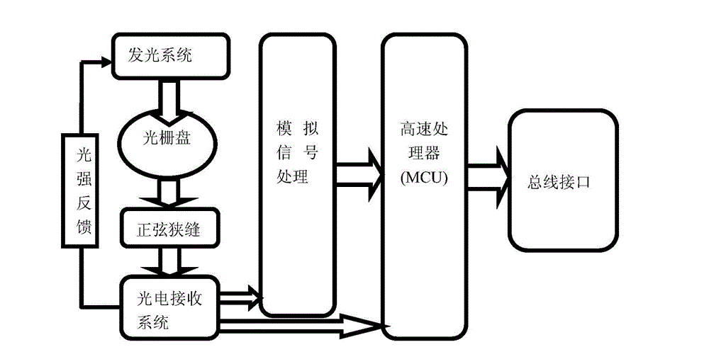
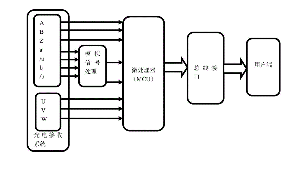
[0038] The light-emitting system outputs A, B, Z square wave digital signals through the slits on the grating disk, and simultaneously outputs differential analog signals a, / a, b, / b, and electrode control signals U, V, W;

[0039] Received by the photoelectric receiving system,

[0040] The analog signals a, / a, b, / b are processed by the analog signal processor and output two differential analog signals Va x , Vb x to the microprocessor MCU,

[0041] The photoelectric receiving system outputs A, B, Z square wave digital signals and electrode control signals U, V, W to the microprocessor MCU;

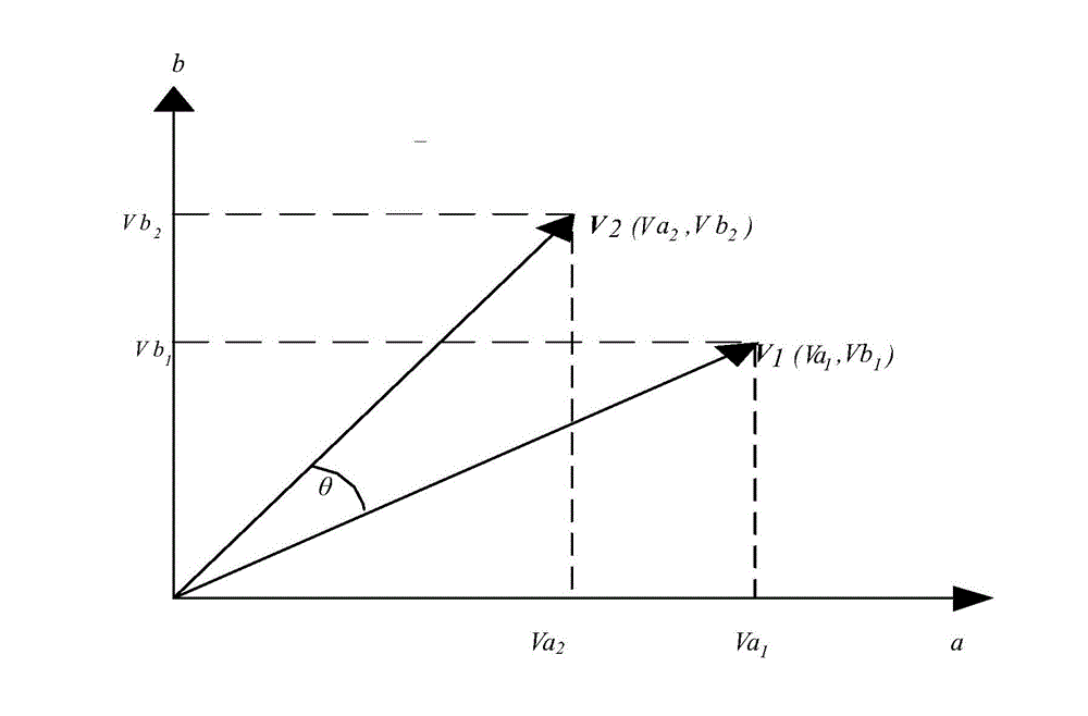
[0042] Microprocessor MCU subdivision method: two-way differential analog signal Va x , Vb x Input to the microprocessor MCU, the analog-to-digital converter AD inside the processor converts the analog signal into a digital signal, and the two converted digital signals are finely subdivided by the CORDIC algorithm, and the vector V 1 Get a n...


PUM


Abstract

The invention relates to a method for realizing a high-resolution incremental bus-based optical-electricity encoder and belongs to optical-electricity encoder realizing methods. The method includes the steps that a square-wave digital signal is output based on the sine slit technology, and two approximately ideal differential analog signals are output at the same time; an increment signal A and an increment signal B participate in subdivision operation, analog and amplification of the two differential analog signals are achieved through two analog operation and amplification devices, analog signals are sent to a microprocessor to be subject to analog-digital conversion after being amplified, and high subdivision is carried out through the CORDIC algorithm; proprietary protocol frames are formed by data obtained after subdivision and electrode control signals U, V and W and output through the RS485 interface or the RS422 interface, wherein multiple protocols such as the Biss protocol, the SSI protocol, the RS485 protocol and the CAN protocol can be compatible at the same time. The electronic subdivision method achieved in this way improves the precision of the encoder and also improves the anti-interference performance and high speed performance of the encoder.

Description

technical field [0001] The invention relates to a realization method of an incremental bus type photoelectric encoder. Background technique [0002] High speed and high precision are the development direction of the field of numerical control, such as numerical control machine tools, textile machinery, elevators, robots, die-cutting machines, engraving machines. The encoder is the most commonly used speed feedback device in motor control. The accuracy of the encoder feedback signal largely determines the speed response and precision of motor control. Commonly used encoders include pulse-type incremental encoders, sin-cosine encoders and serial bus absolute encoders. [0003] The anti-interference ability of the signal transmission signal of the conventional incremental encoder is poor, transmission errors will occur during long-term transmission, the logic judgment is complicated, the color distinction of the cable is not obvious, and it is easy to connect the wrong line. ...

Claims


Application Information

Patent Timeline
IPC IPC(8): G01D5/26
Inventor 王忠杰张宏学
Owner CHANGCHUN YUHENG OPTICS
Learn More