Parallel low-light-loss high-temperature backlight industrial endoscope

A parallel low light loss, high temperature industrial technology, applied in the field of endoscopy, can solve the problem of difficult image and video information collection, and achieve the effects of improved backlight light efficiency, convenient modular replacement, and simple design

Active Publication Date: 2014-02-26
CENT SOUTH UNIV
View PDF13 Cites 12 Cited by
  • Summary
  • Abstract
  • Description
  • Claims
  • Application Information

AI Technical Summary

Problems solved by technology

[0012] The purpose of the present invention is to design a parallel low-light-loss backlight high-temperature industrial endoscope to solve the difficult problem of collecting images and video information inside high-temperature, airtight and dull industrial smelting kilns

Method used


Image

  • Parallel low-light-loss high-temperature backlight industrial endoscope
  • Parallel low-light-loss high-temperature backlight industrial endoscope
  • Parallel low-light-loss high-temperature backlight industrial endoscope

Examples


Embodiment 1

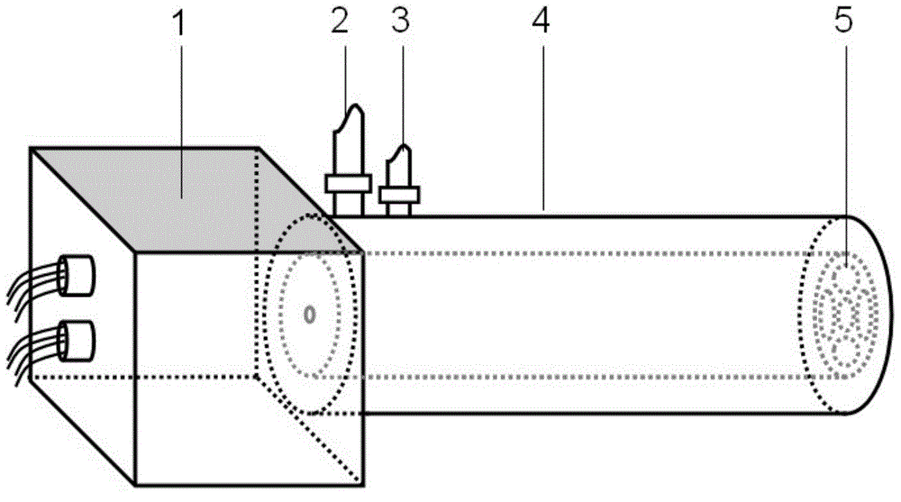
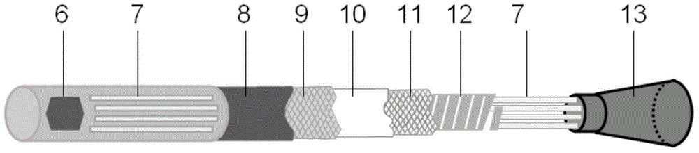
[0050] see figure 1 . Parallel low-light-loss backlight high-temperature industrial endoscope, including an optical eyepiece 13 for taking images in a furnace, a light source light-emitting component 14, a light source driving circuit, a communication circuit, an image guiding fiber bundle 7, a light guiding structure, an imaging driving circuit and a housing The shell is made of 306 steel, including two parts: a round tube 4 and a square shell 1. The square shell is connected to the tail of the cylinder; the length of the round tube is 2 meters.

[0051] A light source driving circuit, an imaging driving circuit for driving the imaging chip 6 and a communication circuit are arranged in the square housing 1 .

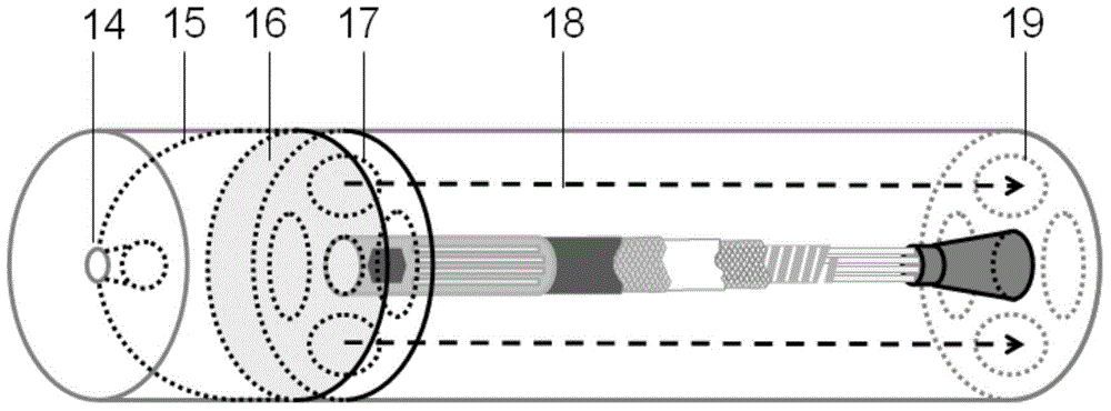
[0052] The tail of the circular tube is provided with a light guide structure, a light source light-emitting part 14, and an imaging chip 6; the light guide structure includes an ellipsoidal concave mirror 15 arranged at the rear of the light source light-emitting part...

Embodiment 2

[0070] The structure of endoscope is the same as embodiment 1.

[0071] The industrial endoscope in this embodiment can be applied to image acquisition of non-high temperature industrial equipment, including steps:

[0072] 1) Install the parallel low-light-loss backlight high-temperature industrial endoscope on the outer wall of the industrial equipment, the front end of the round tube 4 is set inside the equipment, and the square casing 1 is located outside the equipment;

[0073] 2) Start the light source driving circuit to start working, the light source light-emitting part 14 emits light; the light generated by the light source light-emitting part passes through the parallel light generator composed of the ellipsoidal concave mirror 15 and the circular convex lens 16 to form parallel light, and hits the porous light barrier 17 ; the parallel light forms a plurality of light guiding light paths 18 under the action of the porous light shielding plate 17 , and the light pass...


PUM


Abstract

The invention belongs to the field of instrument detection, and provides a parallel low-light-loss backlight high-temperature industrial endoscope. The parallel low-light-loss high-temperature backlight industrial endoscope comprises an optical eyepiece used for obtaining an image in a furnace, a light source luminous part, a light source drive circuit, a communication circuit, an image guide fiber bundle, a light guide structure, an imaging chip, an imaging drive circuit, a cooling system and a shell. The shell comprises a circular tube and a square shell body. The light guide structure comprises an ellipsoidal concave mirror, a round convex lens and a light guide light path, wherein the ellipsoidal concave mirror is arranged on the rear portion of the light source luminous part, and the round convex lens is opposite to the light source luminous part. The front end of the circular tube is provided with the optical eyepiece and a backlight hole, and an image obtaining probe is connected with the imaging chip through the image guide fiber bundle. A novel backlight technology is provided, an original light-guide fiber backlight mode is converted into a parallel light direct backlight mode, the structure of the light path is simplified, the utilization rate of light energy is improved, the backlight area and brightness are increased, constrains to backlight light sources are eliminated, and the parallel low-light-loss high-temperature backlight industrial endoscope is suitable for various light sources, improves stability of equipment and reduces equipment cost.

Description

technical field [0001] The invention belongs to the field of instrument detection, and in particular relates to an endoscope for observing information in a high-temperature furnace. Background technique [0002] With the rapid development of the smelting industry in recent years, it is very difficult to control the industrial kiln required for smelting. The reason is that the internal environment of the kiln is extremely harsh, with high temperature (generally 500 ° C ~ 2500 ° C), high corrosion, high dust, airtight and dull And other characteristics, making the interior of the kiln a black box for the operator, and it is impossible to obtain the operation information in the kiln in real time. Operators can only infer the operating status of the kiln based on indirect measurement data such as temperature, pressure, and flow, and cannot timely and accurately judge the operating status of the kiln and use appropriate control methods to control the kiln, resulting in fluctuatio...

Claims


Application Information

Patent Timeline
Patent Type & Authority Applications(China)
IPC IPC(8): G02B23/24
Inventor 桂卫华陈致蓬蒋朝辉阳春华李晞月邓康许天翔
Owner CENT SOUTH UNIV
Why Eureka
Try Eureka