Pipeline steel welding residual stress prediction method based on ANSYS

A residual stress and prediction method technology, applied in special data processing applications, instruments, electrical digital data processing, etc., can solve the problems of low X-ray penetration, high cost, affecting the accuracy of residual stress measurement, and achieve high analysis efficiency. , saving manpower and high accuracy

Inactive Publication Date: 2014-02-26
HOHAI UNIV CHANGZHOU
View PDF0 Cites 8 Cited by
  • Summary
  • Abstract
  • Description
  • Claims
  • Application Information

AI Technical Summary

Problems solved by technology

The blind hole method will produce processing strain during drilling, which will affect the measurement accuracy of residual stress
The X-ray method can only measure the residual stress on the surface of the material due to

Method used


Image

  • Pipeline steel welding residual stress prediction method based on ANSYS
  • Pipeline steel welding residual stress prediction method based on ANSYS
  • Pipeline steel welding residual stress prediction method based on ANSYS

Examples


Embodiment 1

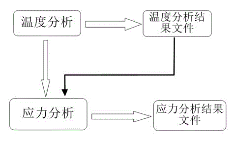
[0028] A method for predicting welding residual stress of X80 pipeline steel based on ANSYS finite element analysis software, comprising the following steps:

[0029] Step (1): Determine the welding conditions, the conditions are: double wire submerged arc welding front wire: I=750A, U=40V; rear wire: I=600A, U=40V; the distance between the front and rear wires is 40mm, and the welding speed is 12mm / s, weldment length 300mm, width 160mm, thickness 20mm;

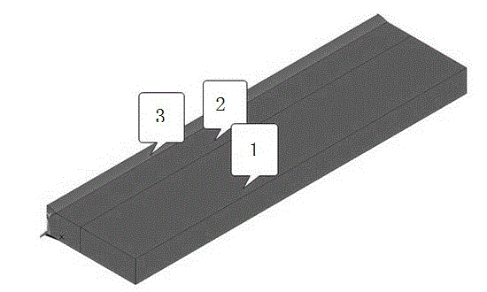
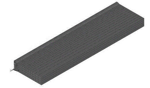
[0030] Step (2): Create a solid model of the weldment and define a SOLID70 unit to sweep and divide the grid; the grid size of the weld area is 2mm, and the heat-affected zone and the base metal area are divided in proportion to the line first, and then swept; the overall It conforms to the rule that the farther away from the weld, the larger the grid size; when the model is a symmetrical model, in order to reduce the amount of calculation, the half plate can be selected for analysis;

[0031] Enter the solution process bel...

Embodiment 2

[0035] A method for predicting welding residual stress of X80 pipeline steel based on ANSYS finite element analysis software, comprising the following steps:

[0036] Step (1): Determine the welding conditions, the conditions are: the welding current of single wire submerged arc welding is 650A, the welding voltage is 40V, and the welding speed is 12mm / s. The weldment is 300mm long, 160mm wide and 20mm thick;

[0037] Step (2): Create a solid model of the weldment, and define a SOLID70 unit to sweep and divide the mesh. Among them, the grid size of the weld area is 2mm, and the heat-affected zone and the base metal area are divided in proportion to the line first, and then swept; the overall conforms to the rule that the farther away from the weld, the larger the grid size, when the model is a symmetrical model , in order to reduce the amount of calculation, the half plate can be selected for analysis;

[0038] Enter the solution process below to calculate the temperature fi...


PUM


Abstract

The invention discloses a pipeline steel welding residual stress prediction method based on ANSYS. The method is characterized by sequentially comprising the following steps that (1) welding piece welding conditions are determined; (2) a solid model of a welding piece is established, an SOLID70 unit dividing scanning net is defined, solving constraint and loading on a welding temperature field are exerted according to practical working conditions; (3) a heat analysis unit SOLID70 is converted into a structure analysis unit SOLID45, the elasticity modulus, the linear expansion coefficient, the Poisson ratio, the yield stress and the elasticity modulus after yield under different temperatures of the welding piece are defined; (4) node temperatures obtained by temperature field analysis are used as loading to be exerted on the structure model, how the constraint conditions are exerted is determined according to model specific situations, and then residual stress distribution is solved. The method is high in analysis efficiency and high in accuracy.

Description

technical field [0001] The invention relates to a stress prediction method, in particular to an ANSYS-based welding residual stress prediction method for pipeline steel. Background technique [0002] At present, pipeline steel is mainly used to transport oil and natural gas in the West-East Gas Pipeline Project, and the uneven heat distribution of pipeline steel during the welding process will lead to the appearance of residual stress after welding. The existence of residual stress, on the one hand, will reduce the strength of the workpiece; on the other hand, it will reduce the fatigue strength and stress corrosion resistance of the material during the subsequent release process, which will cause a series of problems during use. [0003] At present, the methods for measuring residual stress mainly include blind hole method and X-ray diffraction method. The blind hole method will produce processing strain during drilling, which will affect the measurement accuracy of residu...

Claims


Application Information

Patent Timeline
IPC IPC(8): G06F17/50
Inventor 严春妍祁帅史志丹杨顺贞
Owner HOHAI UNIV CHANGZHOU
Why Eureka
Try Eureka