A method for loading and unloading on the same side and an automatic loading and unloading mechanism for realizing the method

A technology of automatic loading and unloading and feeding mechanism, which is applied in the direction of conveyor objects, sustainable manufacturing/processing, electrical components, etc. It can solve problems such as long die bonding time, low manual feeding efficiency, and insufficient die bonding, and achieve high efficiency. And the effect of high degree of automation, saving space for mechanical placement, and improving the utilization rate of the site

Active Publication Date: 2016-05-11
GKG PRECISION MACHINE
View PDF3 Cites 0 Cited by
  • Summary
  • Abstract
  • Description
  • Claims
  • Application Information

AI Technical Summary

Problems solved by technology

The existing die bonding machine mainly works with a single feeding channel, and the die bonding brackets can only be arranged one by one into the feeding channel for die bonding. This method is inefficient, takes a long time to bond the die, and because the feeding channel moves repeatedly in a straight line , so the accuracy of the placement of the die-bonding bracket is high, and a slight deviation or distortion of the die-bonding area on the die-bonding bracket will cause the situation that the die-bonding is not in place or cannot be bonded, resulting in a high defect rate and an increase in cost
Or use a double-station feeding fixture to complete the alternate operation by manual feeding. The efficiency of manual feeding is low, the cycle of die bonding is relatively longer, and there are still certain human factors that cause product loss and increase costs.
Furthermore, in the prior art, a manipulator feeding method is also used. This method has a complicated mechanical structure, which causes an increase in the cost of the enterprise, and is also relatively cumbersome in operation.

Method used


Image

  • A method for loading and unloading on the same side and an automatic loading and unloading mechanism for realizing the method
  • A method for loading and unloading on the same side and an automatic loading and unloading mechanism for realizing the method
  • A method for loading and unloading on the same side and an automatic loading and unloading mechanism for realizing the method

Examples


Embodiment Construction

[0024] The present invention will be described in further detail below in conjunction with the accompanying drawings.

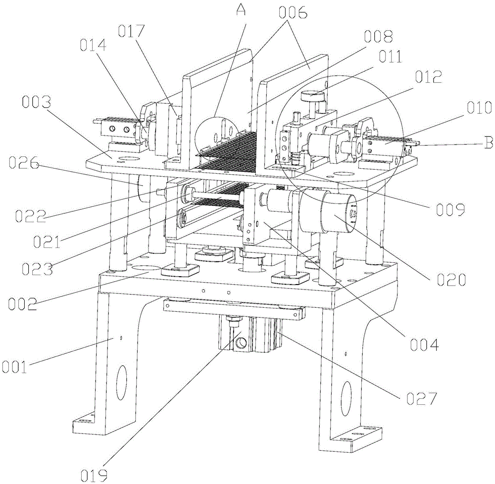
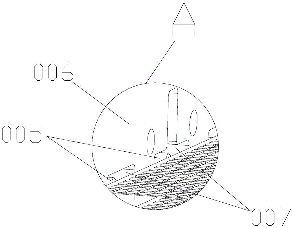
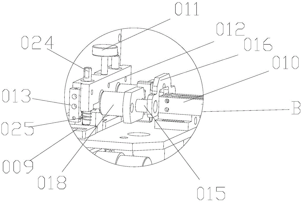
[0025] Figure 1 to Figure 4 The automatic loading and unloading mechanism according to the present invention is schematically shown.

[0026] According to one aspect of the present invention, a method for loading and unloading on the same side is provided, comprising the following steps:

[0027] A. Place the processing material in a stacking space. At this time, the processing material is placed on the bottom layer of the stacking space, and the penultimate processing material is lifted up by the thimble, and the first processing material is still in the stacking space. In the bottom layer of the material space, after the first loading is completed in the same way, the second loading is to release the rest of the processing material by dropping the thimble, and then jack up the third or more processing materials. This cycle realizes the drop type the feed...


PUM


Abstract

The invention discloses a same-side material loading and blanking method and an automatic material loading and blanking mechanism for realizing the above method. A rack, a material stacking mechanism and a blanking mechanism are comprised. A falling-off-type material loading mode is realized through the cooperation of a material distributing thimble and related mechanisms, and accordingly following beneficial effects are obtained: 1, the falling-off-type material loading mode is adopted, and material loading steps can be rapidly carried out; and intelligent automation can be realized, and processing materials can be conveyed continuously, so that the working efficiency of a machinery is raised; 2, through novel structures of a material feeding mechanism and the blanking mechanism, a function of same-side material loading and blanking can be realized, so that connection between the material loading and the blanking is more compact, and synchronization of the material loading and the blanking is realized; the efficiency and the automation degree are high; the same-side material loading can be realized, and a lot of machinery disposing space can be saved, so that the utilization rate of places is better improved; and 3, modes of material loading by manipulators are replaced, so that complex control of the manipulators is avoided. The same-side material loading and blanking method and the automatic material loading and blanking mechanism for realizing the above method are simple in structure, convenient to operate, and the same-side material loading and blanking method and the automatic material loading and blanking mechanism for realizing the above method substantially reduce costs.

Description

technical field [0001] The invention relates to the field of semiconductor packaging equipment, in particular to a same-side loading and unloading method and an automatic loading and unloading mechanism for realizing the method. Background technique [0002] Die bonding machine is an important equipment for the production of light-emitting diodes (LED). Its working process is as follows: firstly, the feeding system transports the die-bonding support in the storage device to the feeding channel, and then the die-bonding support moves along the feeding channel and Stay at a certain position, at this time, the dispensing module on the machine base automatically dispenses the adhesive material, that is, the adhesive material is placed on the die-bonding area of ​​the die-bonding bracket, and then the chip is taken from the wafer by the automatic pick-and-place device. And bonding the chip to the die-bonding area of ​​the die-bonding bracket, the die-bonding is completed. The ex...

Claims


Application Information

Patent Timeline
Patent Type & Authority Patents(China)
IPC IPC(8): H01L31/18H01L21/677
CPCH01L21/67736Y02P70/50
Inventor 邱国良
Owner GKG PRECISION MACHINE
Why Eureka
Try Eureka