Vaulted roof construction
A vault and structure technology, applied in manufacturing tools, furnace crowns/roofs, glass manufacturing equipment, etc., can solve the problems of inability to obtain energy-saving effects, shortened life of thermal insulation bricks, increased radiant heat, etc., to prevent gas leakage in the furnace, Excellent thermal insulation properties and improved airtightness
- Summary
- Abstract
- Description
- Claims
- Application Information
AI Technical Summary
Problems solved by technology
Method used
Image
Examples
no. 1 Embodiment approach
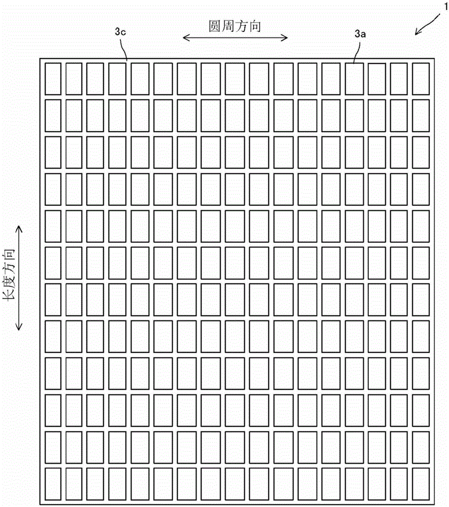
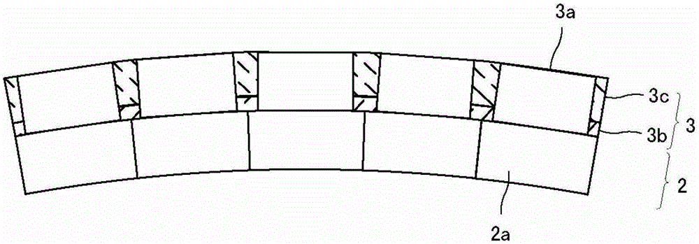
[0033] As described above, the large vault roof structure of the present invention has: a corrosion-resistant layer formed by arranging a plurality of refractory modules in a dome-shaped manner on the inner side of the glass melting furnace; and an air leakage blocking layer. It has a dense material monolithic refractory material provided on the outer surface of the above-mentioned corrosion-resistant layer so as to cover at least the seam of the above-mentioned refractory module. Specifically, as Figure 1A as well as Figure 1B As shown, the large vault roof structure 1 of the present invention is composed of a corrosion-resistant layer 2 formed in a dome shape and an air leakage blocking layer 3 provided on the outer surface of the corrosion-resistant layer 2 .
[0034]Here, the dome shape refers to a shape formed by pushing the arch shape in the horizontal direction, that is, a so-called semi-conical shape. In this specification, the direction forming the arch (arc) in t...
no. 2 Embodiment approach
[0068] Next, a second embodiment of the present invention will be described. overall structure and Figure 1A and Figure 1B The structure described is the same. Here, refer to Figure 3A and Figure 3B Description has a different Figure 2A and Figure 2B Embodiment of the gas leakage blocking layer 13 with the structure of the gas leakage blocking layer 3 shown. here, Figure 3A and Figure 3B are locally enlarged representations Figure 1A and Figure 1B Cutaway view of the top of the large vaulted roof Construct 1. here, Figure 3A is a cross-sectional view viewed from the longitudinal direction, Figure 3B is a cross-sectional view viewed from the circumferential direction.
[0069] This embodiment differs from the first embodiment in that a layer made of a dense amorphous refractory material 13b is formed on the entire outer surface of the refractory module 2a. In this way, if the entire surface is covered with the dense monolithic refractory material 13b, ...
example 1
[0082] First, the furnace shape of the glass melting furnace and the dome structure are implemented with the following sizes.
[0083] Furnace length about 10m
[0084] Furnace width about 6m
[0085] The radius of the big arch is about 6m
[0086] arch angle 60 degrees
[0087] like Figure 1A and Figure 1B As shown, first, on the inner surface side of the furnace, an electroformed brick module made of alumina (Al 2 o 3 95% by mass) The corrosion-resistant layer 2 was constructed in a dome shape under the above conditions so that 21 refractory modules 2 a were provided in the circumferential direction and 16 in the longitudinal direction. Here, as the electroformed brick module, the planar shape of the outer surface viewed from above was a rectangle with a length of about 600 mm in the longitudinal direction, a length of about 320 mm in the circumferential direction, and a module with a thickness of 250 mm. In addition, since this electroformed brick module is used to...
PUM
| Property | Measurement | Unit |
|---|---|---|
| thickness | aaaaa | aaaaa |
| compressive strength | aaaaa | aaaaa |
Abstract
Description
Claims
Application Information
 - R&D
- Intellectual Property
- Life Sciences
- Materials
- Tech Scout
- Unparalleled Data Quality
- Higher Quality Content
- 60% Fewer Hallucinations
Browse by: Latest US Patents, China's latest patents, Technical Efficacy Thesaurus, Application Domain, Technology Topic, Popular Technical Reports.
© 2025 PatSnap. All rights reserved.Legal|Privacy policy|Modern Slavery Act Transparency Statement|Sitemap|About US| Contact US: help@patsnap.com


