Energy-saving air conditioner

An energy-saving air-conditioning and throttling device technology, which is applied in air-conditioning systems, space heating and ventilation, household heating, etc., can solve the problems of high energy consumption in refrigeration systems, and achieve the effects of improved efficiency, stable work, and low energy consumption

Active Publication Date: 2014-03-05
BEIJING FULLLINK OREITH TECH CO LTD
View PDF5 Cites 3 Cited by
  • Summary
  • Abstract
  • Description
  • Claims
  • Application Information

AI Technical Summary

Problems solved by technology

[0003] The purpose of the present invention is to overcome the shortcomings of the prior art, and to solve the problem of large energy consumption in the refrigeration system, to provide an energy-saving air conditioner with simple structure, easy implementation, energy saving and emission reduction, so that evaporation and condensation can achieve isothermal phase Variable evaporation and isothermal phase change condensation

Method used


Image

  • Energy-saving air conditioner
  • Energy-saving air conditioner
  • Energy-saving air conditioner

Examples


Embodiment 1

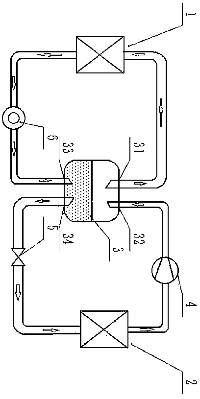
[0024] This embodiment is the workflow of the first energy transport, such as figure 1 The work flow diagram of an energy-saving air conditioner is shown. The whole system includes an outdoor heat exchanger (1), an indoor heat exchanger (2), a liquid storage tank (3), a compressor (4), and a throttling device (5) , circulation pump (6), connecting pipes and circuit control part; the circulation pump (6) is connected between the outdoor heat exchanger (1) and the interface four (34) of the liquid storage tank (3); the compressor (4) Connected between the first port (31) of the liquid storage tank (3) and the indoor heat exchanger (2); the throttling device (5) is connected to the third port (33) of the liquid storage tank (3) and the indoor heat exchanger (2); the outdoor heat exchanger (1), liquid storage tank (3), circulation pump (6) and connecting pipes form an outdoor circulation loop; the indoor heat exchanger (2 ), throttling device (5), liquid storage tank (3), compres...

Embodiment 2

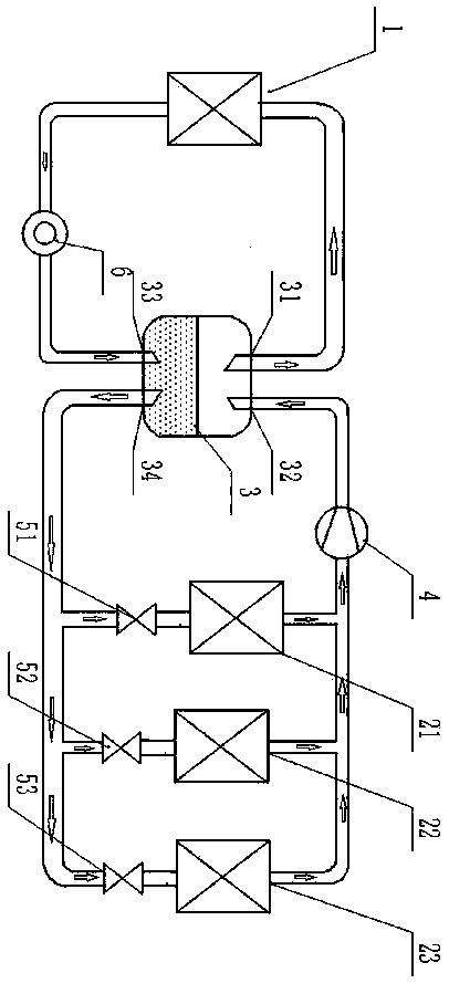
[0026] attached figure 2 It is a schematic structural diagram of the second embodiment of the present invention. Compared with the structure of the first embodiment, the system includes three groups of indoor heat exchangers, and each indoor heat exchanger is connected in series with a separate throttling device. Each group The operating modes of the indoor heat exchangers are the same as those of the first embodiment; other components are the same as those of the first embodiment, and the start-up and operation process are the same as those of the first embodiment.

Embodiment 3

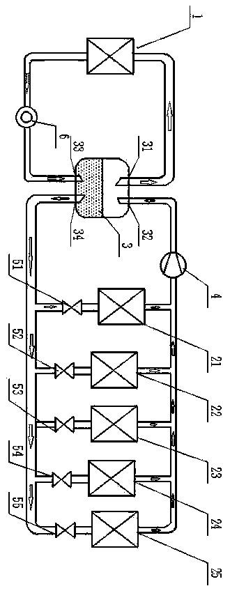
[0028] attached image 3 It is a schematic structural diagram of the third embodiment of the present invention. Compared with the structure of the first embodiment, the system includes five groups of indoor heat exchangers, and each indoor heat exchanger is connected in series with a separate throttling device. The compression The machine is a parallel combination of two compressors; each group of indoor heat exchangers is the same as the operating mode of the first embodiment; the compressor is turned on according to the load demand or two at the same time; other components are the same as the first embodiment, and its start-up and The operation process is the same as that of the first embodiment.


PUM


Abstract

The invention discloses an energy-saving air conditioner which is mainly composed of an indoor heat exchanger, a circulating pump, a liquid storage pot, a compressor, a throttling gear, an outdoor heat exchanger, a connecting pipeline and a circuit control part. The indoor heat exchanger, the throttling gear, the liquid storage pot, the compressor and the connecting pipeline form an indoor circulating loop. The outdoor heat exchanger, the liquid storage pot, the circulating pump and the connecting pipeline form an outdoor circulating loop. The circuit control part controls system operation motions. According to the energy-saving air conditioner, the functions of an evaporator and a condenser are effectively utilized, the evaporator is filled with liquid to the maximum degree to conduct heat absorption and evaporation, the condenser is filled with gas to the maximum degree to conduct heat release and cooling, the problem that the utilization efficiency of an existing evaporator and a condenser is low is solved, and heat transport efficiency is improved.

Description

technical field [0001] The invention belongs to the technical field of air conditioning and refrigeration, and in particular relates to an energy-saving air conditioner. Background technique [0002] At present, the refrigeration cycle technology mainly adopts the Carnot reverse cycle, which consists of four cycle processes: isothermal evaporation of refrigerant, constant entropy compression of refrigerant vapor, isothermal condensation of refrigerant and constant entropy expansion of refrigerant liquid. Correspondingly, the air conditioning system used to regulate the ambient temperature is mainly composed of four components: evaporator, compressor, jet throttling device and condenser. Evaporation, the compressor compresses the refrigerant vapor and enters the condenser for isothermal condensation. During the condensation process, the heat carried by the refrigerant is transferred to the low-temperature air. The refrigerant expands in the throttle valve to complete the cons...

Claims


Application Information

Patent Timeline
Patent Type & Authority Applications(China)
IPC IPC(8): F24F1/00
Inventor 祝长宇丁式平何慧丽
Owner BEIJING FULLLINK OREITH TECH CO LTD
Why Eureka
Try Eureka