Anti-Sniper Detection System

A detection system and sniper technology, applied in radio wave measurement systems, measurement devices, optical device exploration, etc., can solve the problems of inconvenient detection, inability to be widely used, and high cost, and achieve light weight, easy portability, and volume. small effect

Inactive Publication Date: 2016-08-17
西安西光创威光电有限公司
View PDF4 Cites 0 Cited by
  • Summary
  • Abstract
  • Description
  • Claims
  • Application Information

AI Technical Summary

Problems solved by technology

[0006] The above three technologies are easy to expose, not easy to detect, and at the same time, they are relatively expensive and cannot be widely used

Method used


Image

  • Anti-Sniper Detection System
  • Anti-Sniper Detection System
  • Anti-Sniper Detection System

Examples


Embodiment Construction

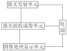
[0029] The anti-sniper detection system provided by the present embodiment utilizes the "cat's eye effect"—the cat's eyes shine brightly in the dark, because the cat's eyes are more reflective to light than other parts of the body. Similarly, the sniper rifle optical sight is more reflective than the surrounding environment, and will produce stronger reflected light under the irradiation of the laser beam. The laser anti-sniper detection system uses this principle to detect enemy snipers.

[0030] The anti-sniper detection optical system scans suspicious combat areas by emitting lasers, analyzes and extracts echo information, and can find enemy tactical targets in the background of the battlefield. Using the so-called "cat's eye" effect to detect the optical window on the equipment used by enemy snipers can achieve fast and accurate positioning of enemy targets. 10 of the background reflectance 2 ~10 4 times to achieve.

[0031] The reflected wave of the "cat's eye" target...


PUM


Abstract

The anti-sniper detection system provided by the present invention includes a power supply, a laser emitting unit, a laser receiving imaging unit, and an image processing and display unit connected to the laser receiving and imaging unit; unit connection. The anti-sniper detection system can quickly and accurately find the location of enemy snipers and provide combatants with precise strike targets.

Description

technical field [0001] The invention belongs to the technical field of laser optics application, and in particular relates to an anti-sniper detection optical system applied to occasions such as conventional operations, peacekeeping, anti-terrorism and security alerts. Background technique [0002] Since the 1990s, photoelectric detection, as an important military detection method, has been applied in the field of anti-sniper confrontation. And laser technology has developed a variety of anti-sniper detection systems, some of which are used in actual combat. According to the detection mechanism of the anti-sniper detection system, it is mainly divided into acoustic detection system, infrared detection system and laser detection system. [0003] (1) The anti-sniper detection system launched by the Third Research Institute of China Electronics Technology Group consists of 1-2 portable array antennas and signal processing units. The system receives the sound wave signal gener...

Claims


Application Information

Patent Timeline
Patent Type & Authority Patents(China)
IPC IPC(8): F41H11/00G01S5/16G01V8/10
Inventor 余炳伟翟欢庆武翅王龙飞罗勇强周瑜哲
Owner 西安西光创威光电有限公司
Why Eureka
Try Eureka