A three-dimensional wind pressure tester

A tester and wind pressure technology, applied in the direction of instruments, pressure difference measurement between multiple valves, measuring devices, etc., can solve problems such as distortion, and achieve the effect of light weight, easy installation, and good portability

Active Publication Date: 2014-03-05
ZHEJIANG UNIV OF TECH
View PDF7 Cites 0 Cited by
  • Summary
  • Abstract
  • Description
  • Claims
  • Application Information

AI Technical Summary

Problems solved by technology

[0003] In order to overcome the limitation and distortion of existing wind pressure test methods in strong wind and rainy weather conditions, the present invention provides a test method with simple test principle, high test accuracy, good frequency response characteristics and stability, and can be widely used in strong wind pressure test methods. Three-dimensional wind pressure tester for wind pressure test on the surface of building structures under wind and rain (such as typhoon) weather conditions

Method used


Image

  • A three-dimensional wind pressure tester
  • A three-dimensional wind pressure tester
  • A three-dimensional wind pressure tester

Examples


Embodiment 1

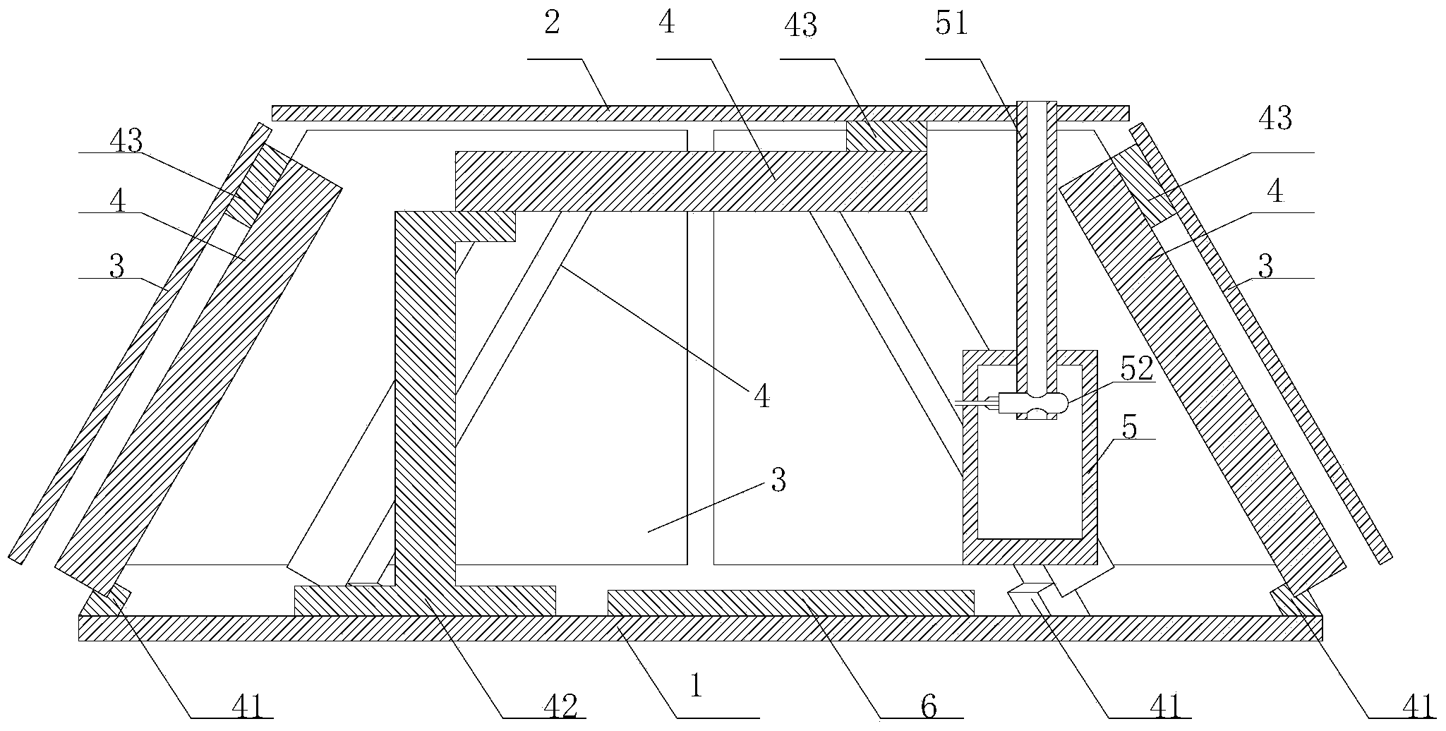
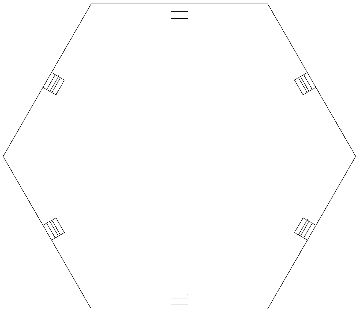
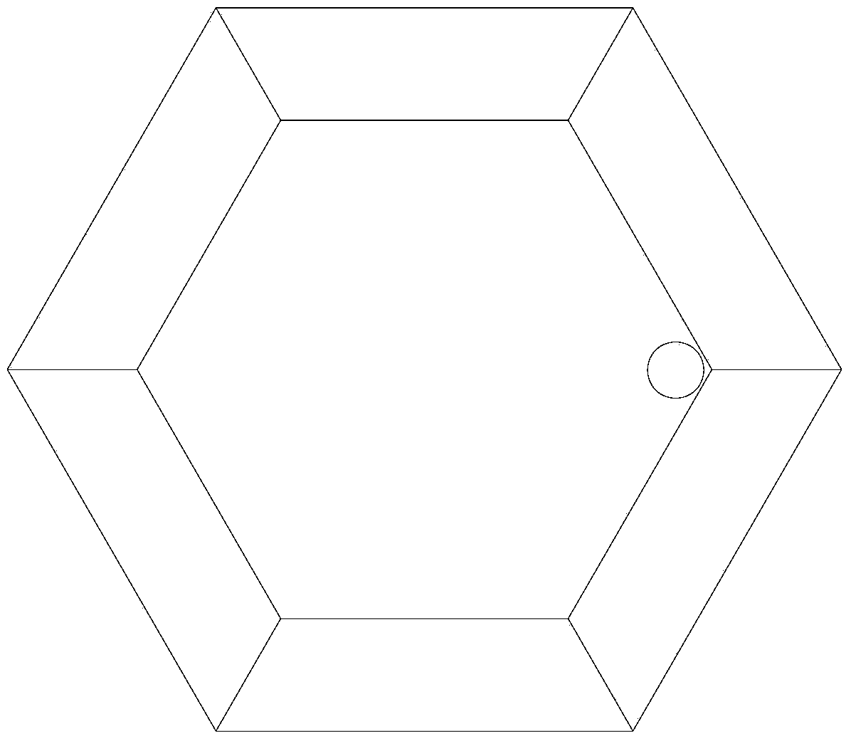
[0025] The shell includes a disc-shaped chassis 1, a regular hexagonal top loaded sheet 2, seven trapezoidal side loaded sheets 3, the chassis 1 and the side loaded sheets 3 There are gaps between the side load-bearing thin plates 3 and the top load-bearing thin plates 1 .

[0026] The chassis 1 is parallel to the top loaded sheet 2, and the angle between each side loaded sheet 3 and the chassis 1 is 60 degrees.

[0027] The bottom of the chassis 1 is equipped with a suction cup.

[0028] Between the chassis 1 and the corresponding single-arm beam mechanical sensor 4, between the top loaded thin plate 2 and the corresponding single-arm beam mechanical sensor 4, between the side loaded thin plate 3 and the corresponding single-arm mechanical sensor The connecting block 43 is glued between the boom mechanical sensors 4 .

[0029] The conduit 51 is perpendicular to the chassis 1 .

[0030] The single-chip microcomputer adopts STM32F103C8T6, has 2 Spi interfaces, 16-channel ADC...

Embodiment 2

[0037] This embodiment is carried out with reference to the wind tunnel test, and the instrument of the present invention is installed on different layers of the test building and different parts of each layer, and the instrument is numbered, and the measured data is automatically stored in the database, thereby obtaining the actual wind pressure of the building, and It can be compared with the data obtained from the wind tunnel test.

[0038] The content described in the embodiments of this specification is only an enumeration of the implementation forms of the inventive concept. The protection scope of the present invention should not be regarded as limited to the specific forms stated in the embodiments. The protection scope of the present invention also includes those skilled in the art. Equivalent technical means conceivable according to the concept of the present invention.


PUM


Abstract

Provided is a three-dimensional wind pressure tester which comprises a bottom disc, a top-surface bearing thin plate, a side-surface bearing thin plate, single-arm mechanics sensors, a sealed cavity, and a single chip microcomputer. The single-arm mechanics sensors are fixed on the bottom disc through a first connecting seat or second connecting seat. The bottom disc, the top-surface bearing thin plate, and the side-surface bearing thin plate respectively correspond to a single-arm mechanics sensor. Connecting blocks are fixed on the single-arm mechanics sensors. The bottom disc, the top-surface bearing thin plate, and the side-surface bearing thin plate are fixed on a corresponding connecting block, respectively. The sealed cavity is installed inside the housing and communicated with external atmosphere through a conduit. A differential pressure sensor is installed on the conduit inserted into the sealed cavity. The single-arm mechanics sensors and the differential pressure sensor are connected with a circuit board. The three-dimensional wind pressure tester has beneficial effects of resolving the distortion and the limitation of a conventional wind pressure testing method under a strong breeze weather condition, and achieving advantages of high testing precision, good stability, simple structure, light weight, easy installation, good portableness, and a networking capability.

Description

technical field [0001] The invention relates to a three-dimensional wind pressure tester. Background technique [0002] Existing wind tunnel tests of building structure models often require the use of relatively large scale models. However, due to the limitation of the cross-sectional area of ​​the wind tunnel and the wind speed, the Reynolds model law in the boundary layer of the wind tunnel is not satisfied, which affects whether the wind tunnel test of the building structure model It can truly and accurately reflect the wind load of the actual building structure. The prototype measurement of wind pressure on the building surface is an extremely important way to solve this problem, and it provides a benchmark and verification for the existing wind tunnel test simulation methods and methods. The existing wind pressure measurement method is to open holes on the surface of the building structure, design the pipeline system, and use the micro-differential pressure sensor to c...

Claims


Application Information

Patent Timeline
Patent Type & Authority Applications(China)
IPC IPC(8): G01L9/00G01L13/00
Inventor 袁伟斌
Owner ZHEJIANG UNIV OF TECH
Why Eureka
Try Eureka