
A Method for Optimizing Power Grid Voltage and Reactive Power Based on Bart Algorithm and Superabsorbing Wall

A grid voltage and optimization method technology, applied in AC network voltage adjustment, reactive power compensation, etc., can solve problems such as difficult and fast training of neural network models, control system switching oscillations, and inability to accurately reflect reactive power components of grid loads, etc.

Active Publication Date: 2016-07-06
GUANGZHOU POWER SUPPLY CO LTD +1
View PDF2 Cites 0 Cited by
  • Summary
  • Abstract
  • Description
  • Claims
  • Application Information

AI Technical Summary

Problems solved by technology

[0003] The literature "Research on Voltage and Reactive Power Control Strategies of Substations under AVC Decentralized Control Mode" lists several voltage and reactive power control strategies commonly used in substations: (1) Control according to the power factor: if the power factor is lower than the lower limit, the capacitor bank will be used, and the high If the upper limit is lower than the upper limit, the capacitor bank will be removed; however, the power factor is only a part of the reactive component and cannot accurately reflect the reactive component of the grid load. (2) Control according to the bus voltage level: mainly adjust the voltage and reactive power based on the voltage level
The defect is that the condition of reactive power balance is not considered. According to the actual operation results, the compensation effect of this method is relatively poor; (3) Comprehensive control based on the nine-area map: the current operating area is judged by real-time voltage and reactive power information, and then based on The control strategy of the nine-area map adjusts gears and switches capacitor banks; in the control strategy of the nine-area map, the boundaries of voltage and reactive power are fixed, which cannot reflect the mutual influence of voltage and reactive power, and there are no restrictions on the use of control equipment. It meets the actual operation requirements and may lead to voltage instability; (4) seek the optimal control strategy based on global planning based on short-term load forecasting. According to the short-term load forecasting value, the transformer tap and capacitor bank maximum The number of actions is the optimization condition, establish the objective function involving the secondary side voltage of the state variable and the reactive power of the incoming line, solve the optimization problem to determine the position of the voltage tap and the switching of the capacitor; the difficulty lies in the establishment and solution of the objective function; (5) based on Fuzzy control of artificial intelligence: extract fuzzy rules on the basis of nine-zone map control, and optimize adjustment strategies
However, the robustness and reliability of fuzzy control are poor, and it is subjective, and cannot make full use of the characteristics of sample data; (6) Artificial neural network control: Introduce the learning and self-adaptive ability of neural network into voltage and reactive power regulation Among the problems, this method has strong fault tolerance, but the structure and operation mode of the power system are constantly changing, and there are not enough training samples, so it is difficult to quickly train the neural network model

Method used


Image

  • A Method for Optimizing Power Grid Voltage and Reactive Power Based on Bart Algorithm and Superabsorbing Wall
  • A Method for Optimizing Power Grid Voltage and Reactive Power Based on Bart Algorithm and Superabsorbing Wall
  • A Method for Optimizing Power Grid Voltage and Reactive Power Based on Bart Algorithm and Superabsorbing Wall

Examples


Embodiment

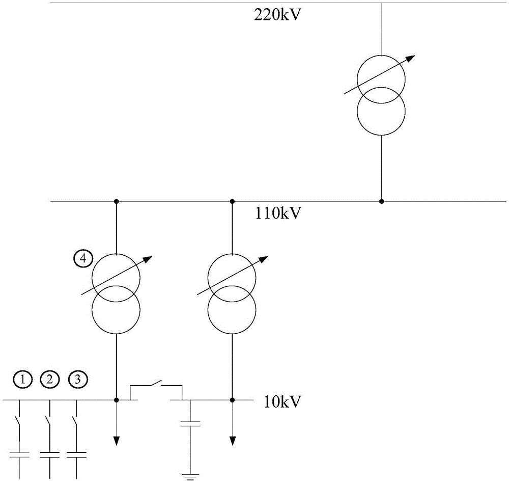
[0068] Such as figure 1 As shown, in order to facilitate the description of the principle of the present invention, a simple system is used as an example. The system consists of a power supply area, ①, ②, ③ are compensation capacitors in this area, and ④ are on-load tapping transformers.

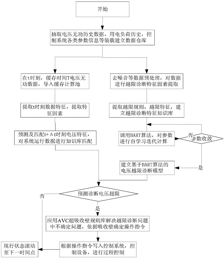
[0069] figure 2 It explains the principle of the grid voltage and reactive power optimization method based on the BART algorithm:

[0070] The first step: First, extract historical data of grid voltage and reactive power, historical data of electricity load, and AVC system fixed values ​​from each system, import and load them into the data warehouse;

[0071] Step 2: Perform pre-processing of noise removal on historical data within a period of time, and extract feature factors for out-of-limit diagnosis of the data;

[0072] The amount of data of the original feature may be very large, or the sample is in a high-dimensional space. The mapping method can be used to represent the sample in a low-dime...


PUM


Abstract

The invention discloses a BART algorithm and super-absorption wall-based reactive power optimization method for the voltage of a power grid. The method comprises the steps of obtaining a primary threshold-crossing mode tendency by using historical data, and establishing a BART-algorithm-based voltage threshold-crossing diagnosis model by utilizing characteristic factors to obtain system characteristics of a current node; establishing a Brown motion model of a voltage time sequence, analyzing characteristics of a motion model of a super-absorption wall of the current node, and carrying out self-learning on parameters; obtaining an operation rule instruction according to the analyzed characteristics of the motion model of the super-absorption wall of the node and current system data characteristics diagnosis results; writing the operation rule instruction into a power system simulation system for simulation in form of constant value, and performing trial running for instruction simulation to realize the constant value. According to the method, voltage and reactive power on the low-voltage side of a transformer are in an ideal low-grid loss state, a complex optimization model is not required to be solved in an optimization process, and the reactive power is flexibly adjusted under the condition of taking the influence of a load, the voltage and the reactive power into full account.

Description

Technical field [0001] The invention belongs to the field of power system relay protection automation, and relates to a grid voltage and reactive power optimization control method, in particular to a grid voltage and reactive power optimization control method based on a BART algorithm and an ultra-absorption wall. Background technique [0002] In the power system, reactive power management is required to ensure that the voltage is within the normal control range and reduce network loss. The factors affecting system voltage and reactive power include engine voltage, transformer tap location, shunt capacitors, reactor banks and system loads. At present, the main equipment used for voltage and reactive power regulation in most substations in my country is on-load voltage regulating transformers and Parallel compensation capacitor bank adjusts voltage and reactive power by adjusting the transformer tap position and switching the parallel capacitor bank. [0003] The document "Research ...

Claims


Application Information

Patent Timeline
Patent Type & Authority Patents(China)
IPC IPC(8): H02J3/16
CPCY02E40/30
Inventor 黄欣高明魏勇军刘有志杨立洪李东旭胡扬叶石罡郭燚
Owner GUANGZHOU POWER SUPPLY CO LTD
Learn More