Method for improving laser preprocessing efficiency of optical element small light spot scanning

A technology for scanning lasers and optical components, which is applied in laser welding equipment, metal processing equipment, welding equipment, etc., can solve the problems of time-consuming and limiting the working efficiency of small-spot scanning preprocessing systems of optical components, and improve efficiency and methods simple and easy effects

Active Publication Date: 2014-03-12
SHANGHAI INST OF OPTICS & FINE MECHANICS CHINESE ACAD OF SCI
View PDF11 Cites 11 Cited by
  • Summary
  • Abstract
  • Description
  • Claims
  • Application Information

AI Technical Summary

Problems solved by technology

During this process, the motor drives the sample to move to each irradiation position and must remain in a static state. After the current irradiation position is irradiated by the laser, the sample moves to the next irradiation position for laser irradiation at the next irradiation position. According to the photo, this traditional sample start-stop start-stop method seriously limits the working efficiency of the small spot scanning pretreatment system of optical components, especially for the large area small spot scanning laser pretreatment process, which is quite time-consuming.

Method used


Image

  • Method for improving laser preprocessing efficiency of optical element small light spot scanning
  • Method for improving laser preprocessing efficiency of optical element small light spot scanning
  • Method for improving laser preprocessing efficiency of optical element small light spot scanning

Examples


Embodiment Construction

[0019] The present invention will be further described below in conjunction with example and accompanying drawing, but should not limit the protection scope of the invention with this.

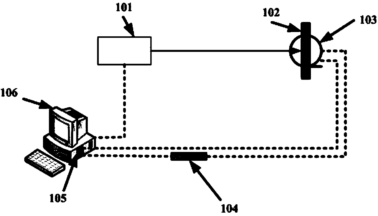
[0020] see figure 1 . figure 1 It is a schematic diagram of the optical element small spot scanning laser pretreatment system adopted by the method of the present invention. In the figure, 101—laser, 102—sample, 103—servo motor, 104—motor driver, 105—movement board, 106—computer.

[0021] The laser 101 outputs laser light, the sample 102 is fixed on the servo motor 103, and the computer 106 controls the motor driver 104 to drive the servo motor 103 to move through the motion board 105, thereby controlling the motion speed and the motion track of the sample 102. At the same time, the The computer obtains the motion situation of the servo motor 103 through the motion board 105, that is, obtains the position information of the sample 102 motion track in real time, and the motion board 105 is ins...


PUM


Abstract

Provided is a method for improving the laser preprocessing efficiency of optical element small light spot scanning. The method comprises the steps that the position coordinates of a movement starting point and a movement terminal point of each line of samples are calculated according to required preprocessing sample area Amm*Bmm and the center-to-center spacing L and the compensation distance L0 of adjacent irradiation light spots; a computer controls the samples to make uniform motion line by line according to the position coordinates and acquires the position information of sample motion trails in real time, and meanwhile the computer controls a laser device to output pulse laser to irradiate the samples to conduct laser preprocessing on the surface of an optical element at a fixed frequency mu. The method is simple and easy to execute, the arraying trajectory of a square or an equilateral triangle on the surfaces of the samples of the adjacent irradiation light spots can be guaranteed, and the working efficiency of laser preprocessing of optical element small light spot scanning is effectively improved.

Description

technical field [0001] The invention relates to an optical element, in particular to a method for improving the pretreatment efficiency of the small light spot scanning laser of the optical element. Background technique [0002] Laser pretreatment technology is an effective means to improve the ability of optical components to resist laser damage. Small spot scanning laser pretreatment can flexibly control the laser beam to irradiate the entire aperture of optical components with the required energy and ideal uniformity, and The system is simple to build and has been favored by the majority of users. Small-spot scanning laser pretreatment is a process of irradiating the surface of the optical element point by point with a certain laser energy flow. Adjacent irradiation spots are required to be arranged in a square or equilateral triangle on the sample surface. In the preprocessing process, the position coordinates of the sample movement corresponding to each laser irradiati...

Claims


Application Information

Patent Timeline
Patent Type & Authority Applications(China)
IPC IPC(8): B23K26/00B23K26/08
CPCB23K26/0853
Inventor 刘晓凤赵元安高妍琦李大伟胡国行易葵
Owner SHANGHAI INST OF OPTICS & FINE MECHANICS CHINESE ACAD OF SCI
Why Eureka
Try Eureka