Cylinder body structure of air and water cooling engine

A water-cooled engine and cylinder block technology, applied in the direction of engine components, machines/engines, cylinders, etc., can solve problems such as poor machining accuracy, increased development and manufacturing costs, and water leakage in the cylinder block, so as to achieve no hidden dangers in water leakage quality and improve reliability in use The effect of improving the connection strength

Active Publication Date: 2014-03-12
LUOYANG NORTHERN ENTERPRISES GROUP
View PDF6 Cites 12 Cited by
  • Summary
  • Abstract
  • Description
  • Claims
  • Application Information

AI Technical Summary

Problems solved by technology

[0007] (1) The structure of the cylinder block leads to a decrease in its heat transfer capacity, which cannot meet the cooling requirements of the tricycle engine
The cylinder liner and the cylinder cooling sleeve are made of two different materials. The heat of the engine is transferred to the cooling water through the two different materials of the cylinder liner and the cylinder cooling sleeve in turn. The thickness is much larger than the wall thickness of the water-cooled engine cylinder liner, which increases the heat transfer resistance of the cylinder liner and reduces the heat transfer capacity of the cylinder block, thus reducing the cooling effect of the engine
(2) The cylinder block has poor manufacturability, which increases development and manufacturing costs
Since the structure of the cylinder block is provided with process openings on the side of the cylinder shell,

Method used


Image

  • Cylinder body structure of air and water cooling engine
  • Cylinder body structure of air and water cooling engine
  • Cylinder body structure of air and water cooling engine

Examples


Embodiment Construction

[0030] Below in conjunction with accompanying drawing and implementation the present invention will be further described:

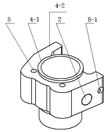
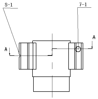
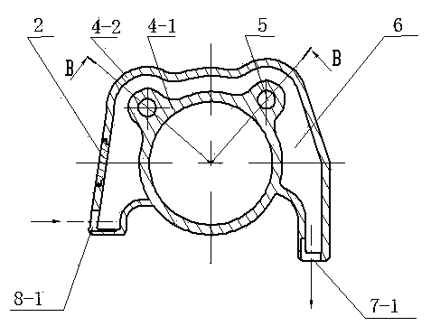
[0031] A cylinder block structure of an air-cooled and water-cooled engine, combining Figure 7 , figure 1 , image 3 , including a cylinder liner and a cylinder housing 3; the cylinder liner is composed of a cylinder liner inner sleeve 4-1 and a cylinder liner outer cover 4-2, wherein the cylinder liner inner sleeve 4-1 and the cylinder liner outer cover 4 -2 together form a closed cooling water cavity 6, and a water inlet I 8-1 and a water outlet I 7-1 are processed on the cylinder liner jacket 4-2. Die-casting molding method is used to wrap a layer of metal material on the outer wall surface of the cylinder liner outer casing 4-2 and part of the outer wall surface of the cylinder liner inner casing 4-1 to form the cylinder shell 3; the cylinder shell 3 is connected with the outer surface of the cooling water cavity , and the outer wall surface of t...


PUM


Abstract

The invention belongs to the technical field of manufacture of engine parts, and relates to a cylinder body structure of an air and water cooling engine. The cylinder body structure is characterized in that a cylinder sleeve is composed of a cylinder sleeve inner sleeve (4-1) and a cylinder sleeve outer sleeve (4-2), wherein a cooling water cavity (6) is composed of an enclosed space formed between the cylinder sleeve inner sleeve (4-1) and the cylinder sleeve outer sleeve (4-2); a wall of the cylinder sleeve inner sleeve (4-1) is provided with at least two cylinder-shaped ear holes (5) which are vertically communicated, and a cylinder body shell (3) and the outer surface of the cooling water cavity (6), the outer wall surface of the cylinder sleeve outer sleeve and part of the outer wall surface of the cylinder sleeve inner sleeve are combined in a non-gap manner. The cylinder body structure provided by the invention has the advantages that the structure design is reasonable and simple, the manufacturability of manufacturing is improved, the manufacturing cost is reduced, the cylinder body structure has another characteristic that the cooling effect is improved, and meanwhile, the water-leaking hidden danger of the cylinder body structure of the existing air and water cooling engine is overcome.

Description

technical field [0001] The invention belongs to the technical field of engine component manufacturing, and in particular relates to a cylinder block structure of an air-cooled and water-cooled engine. Background technique [0002] As the three-wheeled motorcycles are put into use in a large number in China, most of the three-wheeled motorcycles use natural air-cooled engines. The cylinder block of the engine is composed of two parts: the cylinder liner and the cylinder shell. On the outer surface, cooling fins are arranged on the outer surface of the cylinder housing, and the cooling of the engine is realized by the air flow of the three-wheeled motorcycle during running. Since the three-wheeled motorcycles are often used under the conditions of low speed, heavy load and bad road conditions, the low speed of the three-wheeled motorcycles will take away the heat from the engine running under high load, so the natural air-cooled engine cooling system can no longer meet the nee...

Claims


Application Information

Patent Timeline
IPC IPC(8): F02F1/10F02F1/06
CPCF02F1/10
Inventor 张宏刘晨明艾东斌李滨时孟凡科李保明李福全姬战利李艳张鸿领崔湘豫
Owner LUOYANG NORTHERN ENTERPRISES GROUP
Why Eureka
Try Eureka