Radiating heating furnace with annular flue

An annular flue and heating furnace technology, which is applied in the field of heating furnaces, can solve the problems of reducing the utilization rate of combustion heat, hindering the outward transfer and radiation of heat in the furnace, and failing to make full use of the flue, so as to reduce the exhaust temperature and exhaust gas. The effect of smoke heat loss, beneficial to the full utilization of heat, good combustion and heating effect

Active Publication Date: 2014-03-12
中国人民解放军32181部队
View PDF14 Cites 6 Cited by
  • Summary
  • Abstract
  • Description
  • Claims
  • Application Information

AI Technical Summary

Problems solved by technology

[0002] Existing coal-fired stoves are composed of a furnace base, a furnace grate, a furnace, a furnace body and a burner basin, etc. The heat insulation material is filled between the furnace body and the furnace, and the temperature in the furnace and the furnace mouth is relatively high, which is conducive to burning Water is used for cooking, but the heat insulation layer is filled between the furnace body and the hearth, which hinders the heat transfer and radiation in the furnace. The heating mainly depends on the heat release from the chimney. The high-temperature flue gas exits the furnace and is quickly sucked away by the chimney relying on inertial force and draft force. Most of the heat generated by combustion is brought into the external environment by the flue gas, which reduces the utilization rate of combustion heat and significantly reduces the heating effect.
If there is no heat insulation layer between the furnace body and the furnace, the combustion temperature in the furnace will be low, the combustion will be incomplete, and the emission of carbon monoxide and other pollutants will increase significantly.
[0003] Aiming at the shortcoming that the flue of the straight-through flue heating furnace in the prior art is relatively short and cannot make full use of the heat of the flue, the patent application number 200910055688.2 discloses "a high-efficiency heating furnace device", which combines the furnace The chimney is made into a curved design and arranged on the top of the house. This invention has a large heat dissipation area, but the distance between the chimney and the people's activity area is relatively long, and the heating effect is limited.
Patent No. ZL96234090.1 discloses a "high-efficiency coal-saving heating furnace". A conical tempering cover is added to the upper part of the furnace body. The radiation effect is good, but it is easy to leak gas and cause carbon monoxide poisoning.
The patent No. ZL200920031698.8 discloses a "high-efficiency superconducting heating fireplace". A furnace cap with a superconducting radiator is arranged on the upper part of the combustion chamber, but the heat conversion efficiency of this invention is low, and it is easy to accumulate dust and radiate Efficiency drops
The patent application No. 03211465.6 discloses a "double furnace back-type flue heating furnace", which adopts a double-layer furnace body, and there is a flue between the cylindrical furnace body water layer and the cylindrical flue water layer, and the flue surrounds The furnace body is round, with a large internal and external heating area and fast heating. However, the structure of this patent is complex, and a water pump needs to be installed for heating. In the event of a power failure or other accident, heating cannot be provided, and an external power supply is required. It is not suitable for outdoor or remote areas without electricity.
[0004] In view of the fact that some heating furnaces need to be externally connected to the mains power supply, which causes many inconveniences in use and installation, the patent 201110331304.2 discloses "a fireplace with a power generation device". A power generation component that converts the temperature difference into electrical energy, and the power generation component has an output terminal that can provide working power for the load
However, in the fireplace with power generation device, the temperature in the furnace is reduced when the power generation component is used to generate electricity, resulting in insufficient combustion and reduced combustion efficiency. At the same time, the layout area of ​​the patented power generation component is limited, the cold end relies on natural convection cooling, and the temperature difference between the cold and hot ends is small. , power generation efficiency and low efficiency

Method used


Image

  • Radiating heating furnace with annular flue
  • Radiating heating furnace with annular flue
  • Radiating heating furnace with annular flue

Examples


Embodiment Construction

[0024] The present invention will be further described in detail below in conjunction with the accompanying drawings.

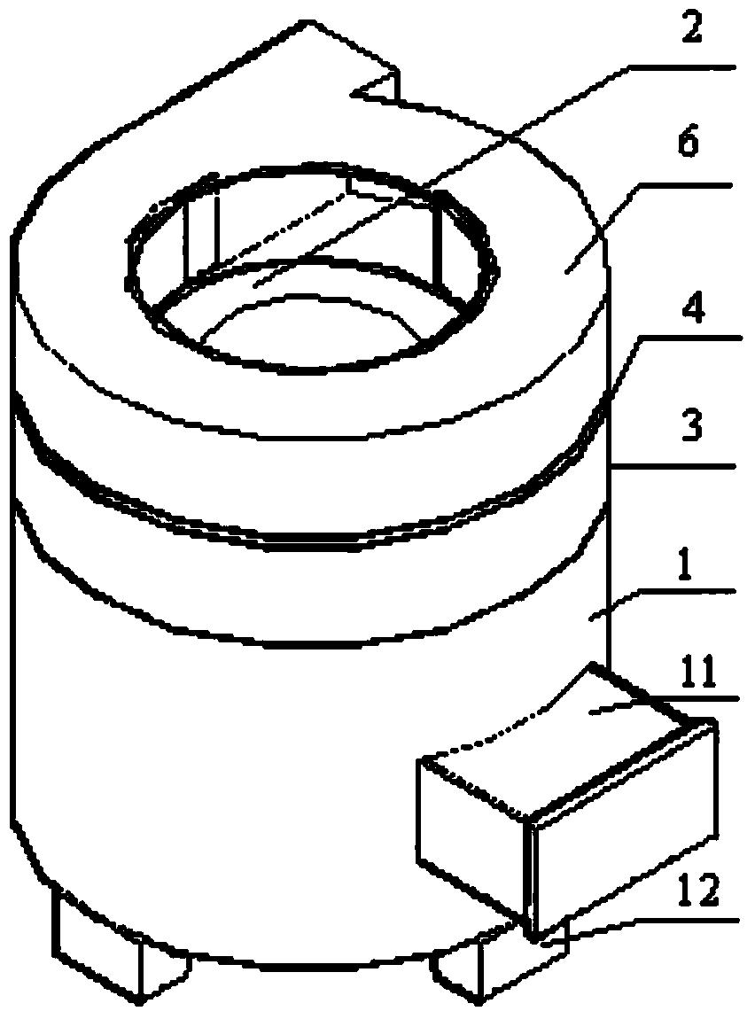
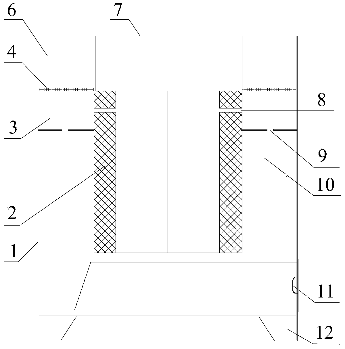
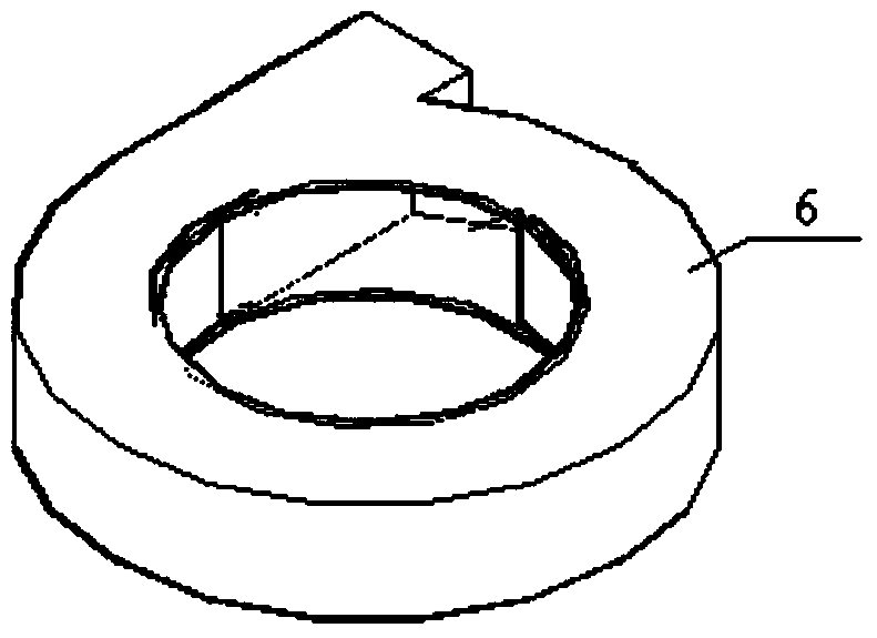
[0025] Such as Figure 1-4 As shown, the present invention includes a furnace body 1, the upper part of the furnace body 1 is provided with an air supply channel 3 with an air inlet, the bottom of the air supply channel 3 is provided with a number of primary air inlet holes 9, and the inner wall of the air supply channel 3 is provided with a number of The secondary air inlet 8 and the primary air inlet 9 communicate with the bottom of the furnace 2 through the primary air inlet passage 10 between the outer wall of the furnace 2 and the furnace body 1, and the upper part of the air supply passage 3 is provided with an annular shape communicating with the furnace 2 The flue 6, the flue 6 is connected to the furnace 2 through the smoke inlet, the secondary air inlet 8 is directly connected to the upper part of the furnace 2, and a number of thermoelectric modules 4...


PUM


Abstract

The invention discloses a radiating heating furnace with an annular flue. The radiating heating furnace comprises a furnace body, an air supply channel with an air inlet is arranged on the upper portion of the furnace body, a plurality of primary air inlet holes are formed in the bottom of the air supply channel, a plurality of secondary air inlet holes are formed in the inner wall of the air supply channel, a primary air inlet channel is formed between the outer wall of a hearth and the inner wall of the furnace body, the primary air inlet holes are communicated with the bottom of the hearth through the primary air inlet channel, the secondary air inlet holes are directly communicated with the hearth, the annular flue is arranged on the upper portion of the air supply channel, the flue is communicated with the hearth through a smoke inlet, a plurality of thermoelectricity modules generating electricity through temperature difference are arranged between the flue and the air supply channel, and an air blower powered by the thermoelectricity modules is arranged on the air inlet. The radiating heating furnace with the annular flue has the good combustion and heating effects in high-altitude regions, and is suitable for being used in the high-altitude regions. According to the radiating heating furnace with the annular flue, when smoke passes through the secondary air inlet holes, unburned smoke is combusted again, the hearth and smoke temperature rises, the radiating efficiency of the annular flue is improved, the heating efficiency is high, and the using and maintenance cost is low.

Description

Technical field [0001] The invention relates to a heating stove, in particular to an annular flue radiation heating stove. Background technique [0002] The existing coal-burning stove is composed of a furnace base, a grate, a furnace, a furnace body, and a furnace head basin. The furnace body and the furnace are filled with thermal insulation materials. The temperature in the furnace and the furnace mouth is relatively high, which is beneficial for burning. Water for cooking, but the heat insulation layer is filled between the furnace body and the furnace, which hinders the heat transfer and radiation in the furnace. Heating mainly relies on the chimney to release heat. The furnace outlet is closer to the chimney and the chimney is in the furnace plate. The high-temperature flue gas from the furnace is quickly evacuated by the chimney by inertial force and suction force. Most of the heat generated by combustion is brought into the external environment by the flue gas, which redu...

Claims


Application Information

Patent Timeline
Patent Type & Authority Applications(China)
IPC IPC(8): F24B1/19F24B1/191
Inventor 高怀斌李洪峻黄光宏李俊胡云俊
Owner 中国人民解放军32181部队
Why Eureka
Try Eureka