
A kind of slow descender damping device for metal particle medium

A metal particle and damping device technology, applied in life-saving equipment, building rescue, etc., can solve the problems of high cost, high requirements on assembly accuracy and airtightness, fear of water, etc., and achieves anti-corrosion, assembly accuracy and low requirements on mechanism airtightness. , the effect of low overall cost

Active Publication Date: 2016-01-20
淮安市清江浦区市场监管综合服务中心
View PDF11 Cites 0 Cited by
  • Summary
  • Abstract
  • Description
  • Claims
  • Application Information

AI Technical Summary

Problems solved by technology

The frictional damping device is mainly composed of a driving part that drives the centrifugal body to rotate and a friction pair (between the centrifugal body and the inner circular surface of the box). The problem is that the descending device using the frictional damping device is afraid of water and oil. When media such as water and oil enter between the friction pairs, the damping effect is greatly reduced, and even the slow down effect fails
The problem is that the overall structure is relatively complex, the requirements for assembly accuracy and airtightness after long-term storage are relatively high, and the cost is also high

Method used


Image

  • A kind of slow descender damping device for metal particle medium
  • A kind of slow descender damping device for metal particle medium
  • A kind of slow descender damping device for metal particle medium

Examples


Embodiment 1

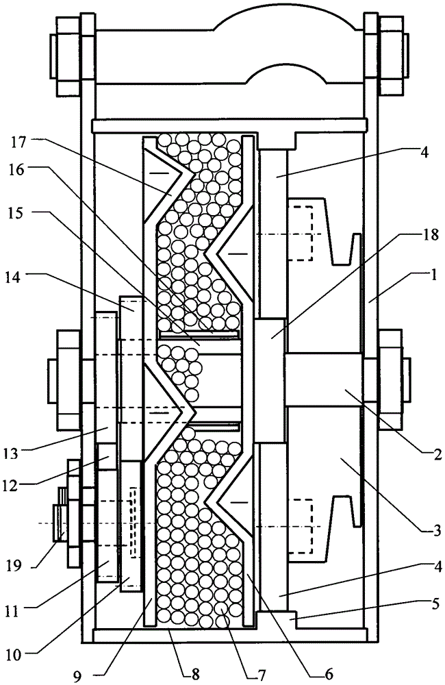
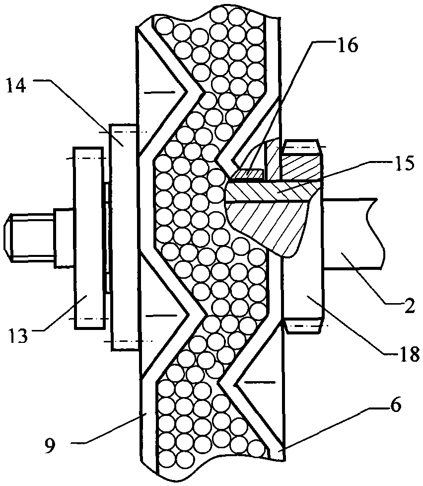
[0025] figure 2 A schematic diagram of the local structure of a slow descender damping device for granular media (hereinafter referred to as the damping device) provided by the present invention. descender such as figure 1 shown. The structure, assembly relationship and working principle of this damping device are as follows:

[0026] Such as figure 1 As shown, the rope winding mechanism mainly includes the rope wheel 3 and the central shaft 2; the speed-up mechanism includes the planetary gear 4, the ring gear 5 and the central gear 18; as figure 1 , Figure 7 As shown, the counter gear set is mainly composed of counter driving gear 13, gear A12, gear B11, gear C10 and counter driven gear 14.

[0027] exist figure 1 Among them, the sheave 3 is movably assembled with the central shaft 2, and the gear shafts of the planetary gears 4 (2 or 3) are fixedly installed on the sheave 3, and the planetary gears 4 mesh with the inner ring gear 5 of the box body respectively, ...

Embodiment 2

[0032] Such as Figure 8 As shown, compared with the slow descender of embodiment 1, the entire slow descender has a rope winding mechanism, a gear speed-up mechanism, and a damping device that are not on the same central axis, but are arranged in parallel and separated and connected to each other. In the entire descender, all the gears are ordinary cylindrical gears with external meshing. The advantage is that it is easy to process and manufacture, and the cost is low. The disadvantage is that the overall size of the descender is slightly larger, but the speed ratio can achieve a larger value. In this embodiment The rotational speed ratio of the rope wheel 3 and the damping wheel is 1:6. The counter gear set has been simplified, and mainly consists of a counter driving gear 13 and a counter driven gear 14 . The rope wheel 3 directly drives the forward damping wheel 6 to rotate through the speed-up gear on the left, and the rope wheel 3 drives the reverse damping wheel 9 to r...


PUM


Abstract

The invention discloses a descent controller damping device for a metal particle medium. A forward direction damping wheel and a reverse direction damping wheel are movably assembled inside the inner circle face of a box body at the same time, are opposite to each other at a certain interval and rotate in the reverse directions, wherein the diameter of the forward direction damping wheel and the diameter of the reverse direction damping wheel are equal, the opposite inner side faces of the two damping wheels are provided with a plurality of protruding edges which are evenly distributed, the part between the two damping wheels is filled with a certain number of steel balls, when the two damping wheels are driven by a rope winding mechanism or an acceleration mechanism of the rope winding mechanism to reversely rotate, the steel balls mutually collide and are squeezed with one another through the protruding edges on the side faces of the damping wheels, the damping function is formed for the rotation of the two damping wheels and cannot be effected or be out of operation even when water, oil and other lubricating media are added, the damping effect is obvious, and manufacturing cost is low.

Description

technical field [0001] The invention relates to a high-altitude slow-descent device, in particular to a metal particle medium slow-descent device damping device. Background technique [0002] The high-altitude lifesaving descending device in the prior art generally consists of three parts, namely a rope winding mechanism, a speed-increasing mechanism (gear set) and a damping device. Most of the damping devices are friction type, that is, the centrifugal force of the high-speed rotating parts (centrifugal body) causes friction between the friction pairs, limits the rotation speed of the rope winding mechanism, and achieves the purpose of slowing down. The frictional damping device is mainly composed of a driving part that drives the centrifugal body to rotate and a friction pair (between the centrifugal body and the inner circular surface of the box). The problem is that the descending device using the frictional damping device is afraid of water and oil. If water, oil and o...

Claims


Application Information

Patent Timeline
Patent Type & Authority Patents(China)
IPC IPC(8): A62B1/10
Inventor 房丽敏吕雪寒刘化岭
Owner 淮安市清江浦区市场监管综合服务中心
Learn More