
Wind power generation, thermal power generation and compressed air energy storage integrated power generation system

A technology of compressed air energy storage and power generation system, which is applied in wind power generation, wind power engine, wind power motor combination, etc. It can solve the problems of non-compliance with green energy development requirements, rising fossil fuel prices, etc., and improve peak-shaving capability and power grid security performance, improve peak-shaving and valley-filling capabilities, and start-up quickly

Inactive Publication Date: 2014-03-19
NORTH CHINA ELECTRIC POWER UNIV (BAODING)
View PDF3 Cites 34 Cited by
  • Summary
  • Abstract
  • Description
  • Claims
  • Application Information

AI Technical Summary

Problems solved by technology

Traditional compressed air energy storage systems have the advantages of large energy storage capacity, long energy storage period, high efficiency and relatively small unit investment; however, compressed air energy storage systems still rely on burning fossil fuels to provide heat sources. The threat of depletion and rising prices, on the other hand, its combustion still produces nitrogen oxides, sulfides and carbon dioxide, etc., which do not meet the requirements of green energy development

Method used


Image

  • Wind power generation, thermal power generation and compressed air energy storage integrated power generation system
  • Wind power generation, thermal power generation and compressed air energy storage integrated power generation system
  • Wind power generation, thermal power generation and compressed air energy storage integrated power generation system

Examples


Embodiment Construction

[0020] The present invention will be described in further detail below in conjunction with the accompanying drawings and specific examples.

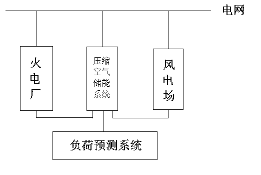
[0021] figure 1 It is a schematic diagram of the integrated system of wind farm, thermal power plant and compressed air energy storage. The compressed air energy storage system is connected to the wind farm, the thermal power plant, and the load forecasting system respectively. At the same time, the wind farm, the thermal power plant, and the compressed air energy storage system are respectively connected to the power grid. The load forecasting system issues instructions to the compressed air energy storage system by predicting the grid load and the wind farm, thermal power plant, and compressed air energy storage system power.

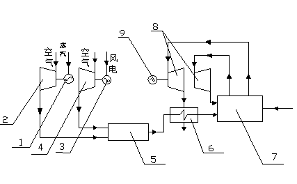
[0022] figure 2 It is a schematic diagram of the operation of the wind farm, thermal power plant, and compressed air energy storage integrated system. The compressed air energy storage system is connected to...


PUM


Abstract

The invention discloses a wind power generation, thermal power generation and compressed air energy storage integrated power generation system. The integrated system is mainly composed of a wind power plant, a thermal power plant and a compressed air energy storage power station. The wind power plant and the thermal power plant are connected through a compressed air system to form a wind power, thermal power and energy storage integrated power generation system. The compressed air energy storage system adjusts power output according to a grid load requirement and the output condition of the wind power plant and the thermal power plant to achieve linkage of the wind power plant and the thermal power plant and improve grid load response capability. Under the condition that grid safety is ensured, more clean energies can be connected into a grid. The compressed air energy storage system utilizes high temperature slag generated by the thermal power plant to generate power and replaces the traditional way that a traditional compressed air energy storage system utilizes natural gas to generate power. Therefore, the system has high environment benefit. Meanwhile, the system is high in peak load adjustment capability. By means of the system, the grid can receive wind power in a large scale, and the peak adjustment capability can be improved.

Description

technical field [0001] The invention belongs to the field of power generation utilizing renewable energy, in particular to an integrated power generation system of wind power generation, thermal power generation and compressed air energy storage. Specifically, the compressed air energy storage system is mainly used to connect wind farms and thermal power plants. The compressed air energy storage system adjusts its power output according to the load demand of the grid and the output of wind farms and thermal power plants. In this way, the linkage between wind farms and thermal power plants can be realized, the response ability to the grid load can be improved, and more clean energy can be accepted and connected to the grid while ensuring the safety of the grid. Background technique [0002] The development and utilization of earth's energy is still a major issue in the world today. While constantly developing new energy, how to use existing energy more effectively has becom...

Claims


Application Information

Patent Timeline
Patent Type & Authority Applications(China)
IPC IPC(8): F03D9/02F01D15/10F01K27/02F04C23/02
CPCY02E60/15Y02E10/72
Inventor 何青刘辉
Owner NORTH CHINA ELECTRIC POWER UNIV (BAODING)
Learn More