
High temperature pressure sensor and preparation method thereof

A pressure sensor, high temperature technology, applied in the direction of fluid pressure measurement by changing the ohmic resistance, can solve the problems of product failure, rise, no record of PN junction leakage current, etc., and achieve the effect of high reliability

Active Publication Date: 2016-09-21
CHINA RESOURCES MICROELECTRONICS (CHONGQING) CO LTD
View PDF7 Cites 0 Cited by
  • Summary
  • Abstract
  • Description
  • Claims
  • Application Information

AI Technical Summary

Problems solved by technology

Although this patent document records a technical solution related to the use of PN junctions to prepare sensors, it does not record how to solve the problem of how to solve the problem of how to solve the problem of how to solve the problem of how to solve the problem of how to solve the problem of how to solve the problem of how to solve the problem of increasing the leakage current caused by the PN junction with the increase of the working environment temperature, which in turn leads to the failure of the product.

Method used


Image

  • High temperature pressure sensor and preparation method thereof
  • High temperature pressure sensor and preparation method thereof
  • High temperature pressure sensor and preparation method thereof

Examples


Embodiment Construction

[0048] The specific embodiment of the present invention will be further described below in conjunction with accompanying drawing:

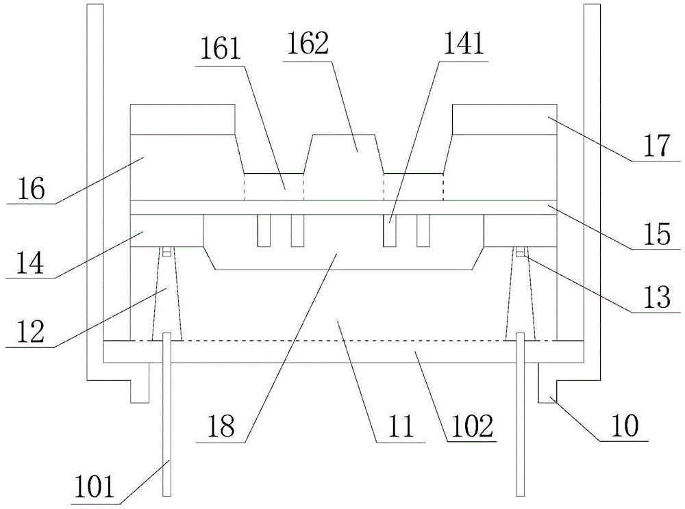
[0049] figure 1 It is a structural schematic diagram of an embodiment of the high temperature pressure sensor of the present invention; as figure 1 Shown, a high temperature pressure sensor, including:

[0050]A base 10 made of a metal material (such as stainless steel) is provided with a base glass 102 sintered with glass glue; preferably, the above-mentioned base 10 is hollow cylindrical to be sleeved on on the base glass 102, and the base 10 is also provided with an inwardly convex protruding structure for supporting the edge portion of the base glass 102, that is, the middle part of the base glass 102 is not in contact with the base 10, and then The base glass 102 and the base 10 form a barrel-shaped structure, the base glass 102 serves as the bottom of the barrel-shaped structure, and the base 10 serves as the sidewall of the barrel-shaped ...


PUM


Abstract

The invention relates to the field of MEMS manufacturing, in particular to a high-temperature pressure sensor and a preparation method thereof. Based on a silicon-on-insulator substrate, a Whist bridge structure is formed on its front side, and a pressure-sensitive film is formed on its back side. Anodic bonding of silicon-glass forms a vacuum cavity, and silicon-glass bonding is used on the back to achieve stress balance, or a single-chip anodic bonding process is used, and finally a pressure sensor with high reliability is prepared by single-chip packaging.

Description

technical field [0001] The invention relates to the field of MEMS manufacturing, in particular to a high-temperature pressure sensor and a preparation method thereof. Background technique [0002] Micro-Electro-Mechanical System (MEMS for short) refers to a micro-device or micro-device that can be mass-produced and integrates micro-mechanisms, micro-sensors, micro-actuators, signal processing and control circuits, up to interfaces, communications and power supplies. System; MEMS has the advantages of small size, light weight, low power consumption, good durability, low price, stable performance, etc., and is widely used in many fields. [0003] The MEMS micro-bridge structure is a bridge structure formed by using a sacrificial layer release process, and is widely used in MEMS sensors, such as diffused silicon piezoresistive pressure sensors. [0004] The traditional manufacturing process of diffused silicon piezoresistive pressure sensors generally uses P-N junctions to iso...

Claims


Application Information

Patent Timeline
Patent Type & Authority Patents(China)
IPC IPC(8): G01L9/06
Inventor 陈敏马清杰
Owner CHINA RESOURCES MICROELECTRONICS (CHONGQING) CO LTD
Learn More