All-solid LMA (large mode area) photonic band gap optical fiber

A photonic bandgap and large mode field technology, applied in cladding optical fiber, optical waveguide and light guide, etc., can solve the problem of difficult large mode field transmission, and achieve the effect of low binding loss, low bending loss and regular mode field

Inactive Publication Date: 2014-03-19
JIANGSU UNIV
View PDF5 Cites 15 Cited by
  • Summary
  • Abstract
  • Description
  • Claims
  • Application Information

AI Technical Summary

Problems solved by technology

This fiber can obtain a mode field area of ​​500 μm2 at a wavelength of 1064 nm and a bending radius of 10 cm, but the bending radius must be fixed within a small range to ensure single-mode transmission
It is still difficult for photonic bandgap fibers to achieve large mode field transmission with a mode field area above 1000 μm2 at a wavelength of 1064 nm

Method used


Image

  • All-solid LMA (large mode area) photonic band gap optical fiber
  • All-solid LMA (large mode area) photonic band gap optical fiber
  • All-solid LMA (large mode area) photonic band gap optical fiber

Examples


Embodiment 1

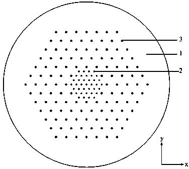
[0047] figure 1 A schematic cross-sectional view of one embodiment of the invention is given. The matrix material is pure quartz, and the material of the high-refractive-index medium column and the low-refractive-index medium column is doped quartz material. Among them, the period Λ of the low refractive index dielectric column (2) l =5.5 μm, diameter d l =1.2 μm, refractive index n l =1.44; the period Λ of the high refractive index medium column (3) h =11 μm, diameter d h =1.8 μm, the refractive index n h =1.48; the refractive index of the matrix material (1) n b =1.45. That is, the fiber core is formed by missing 7 high-refractive-index dielectric columns (3) in the periodic grid, and then arranging low-refractive-index dielectric columns (2), that is, m=2, N=2, and the low-refractive-index dielectric columns ( 2) The number of layers is 2×2-1=3. When the bending radius is 16-52 cm, the bending loss of the high-order mode of the fiber is greater than 10 dB / m, while ...

Embodiment 2

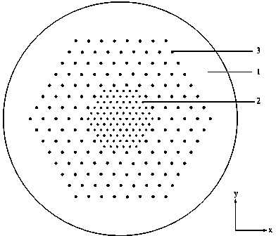
[0049] In order to further increase the mode field area of ​​the fiber, figure 2 A cross-sectional view of another embodiment of the invention is shown. The period Λ of the low refractive index dielectric column (2) l =5.5 μm, diameter d l =1.2 μm, refractive index n l =1.436; period Λ of high refractive index medium column (3) h =11 μm, diameter d h =1.8 μm, the refractive index n h =1.48; the refractive index of the matrix material (1) n b =1.45. That is, the fiber core is formed by missing 7 high-refractive-index dielectric columns (3) in the periodic grid, and then arranging low-refractive-index dielectric columns (2), that is, m=3, N=2, and the low-refractive-index dielectric columns ( 2) The number of layers is 3×2-1=5. When the bending radius is 24-32 cm, the bending loss of the high-order mode of the fiber is greater than 10 dB / m, while the bending loss of the fundamental mode is less than 0.1 dB / m. It can be considered that the fiber can transmit single-mode ...

Embodiment 3

[0051] This embodiment provides a large mode field bandgap fiber that can be transmitted in a single mode without bending under a straight fiber. Its cross-sectional diagram is shown in figure 1 shown. Among them, the period Λ of the low refractive index dielectric column (2) l =5.5 μm, diameter d l =1.2 μm, refractive index n l =1.434; period Λ of high refractive index medium column (3) h =11 μm, diameter d h =1.8 μm, the refractive index n h =1.48; the refractive index of the matrix material (1) n b =1.45. That is, the fiber core is formed by missing 7 high-refractive-index dielectric columns (3) in the periodic grid, and then arranging low-refractive-index dielectric columns (2), that is, m=2, N=2, and the low-refractive-index dielectric columns ( 2) The number of layers is 2×2-1=3. Its mode field area can reach 693 μm 2 .


PUM


Abstract

The invention discloses an all-solid LMA photonic band gap optical fiber. The all-solid LMA photonic band gap optical fiber comprises fiber core and cladding, wherein the fiber core comprises base materials (1) and low-reflective-index medium columns (2) which are distributed in a regular-triangular grid; the cladding comprises the base materials (1) and high-reflective-index medium columns (3). The all-solid LMA photonic band gap optical fiber binds light through the high-reflective-index medium columns, thereby having relatively strong binding capacities and relatively low bending losses; the low-reflective-index medium columns distributed cyclically in the center of the optical fiber can enlarge the loss difference between fundamental modes and high-order modes to distinguish the fundamental modes from the high-order modes and to further enable the optical fiber to achieve single-mode transmission. Due to the fact that the low-reflective-index medium columns are of a multi-layer structure, the optical fiber can obtain a large mode area. Meanwhile, the all-solid LMA photonic band gap optical fiber is of an all-solid structure and accordingly avoids the difficulty in manufacturing and usage of micro-structure optical fibers with air holes, and can achieve LMA low-bending-loss single-mode transmission.

Description

technical field [0001] The invention relates to the field of fiber lasers, in particular to an all-solid-state large-mode field photonic bandgap fiber with large mode field area and low bending loss characteristics. Background technique [0002] High-power fiber lasers have more and more applications in industry due to their advantages of good beam quality, small size, high conversion efficiency and good heat dissipation. However, high-power lasers can cause problems such as optical damage and nonlinear effects. The use of large-mode-field fibers can suppress nonlinear effects and increase the optical damage threshold. Generally, the basic requirements for large mode field fibers are: 1. Single-mode operation, which is a basic condition for high-performance lasers; 2. Large mode field area; 3. Low bending loss, that is, the fiber can allow a certain degree of bending, and Has low bending loss. [0003] There are several technical ways to increase the fiber mode area: [...

Claims


Application Information

Patent Timeline
Patent Type & Authority Applications(China)
IPC IPC(8): G02B6/02
Inventor 陈明阳龚天翼
Owner JIANGSU UNIV
Why Eureka
Try Eureka