Handheld video equipment
A technology of video equipment and casing, applied in the field of handheld video equipment, can solve the problems of inconvenient portability and use of video systems, limited application occasions, etc., and achieve the effects of improving utilization rate, reducing light loss, and being easy to carry.
- Summary
- Abstract
- Description
- Claims
- Application Information
AI Technical Summary
Problems solved by technology
Method used
Image

Examples
Embodiment 1
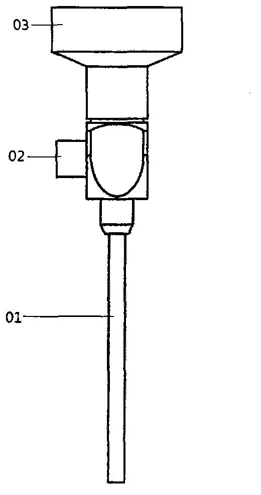
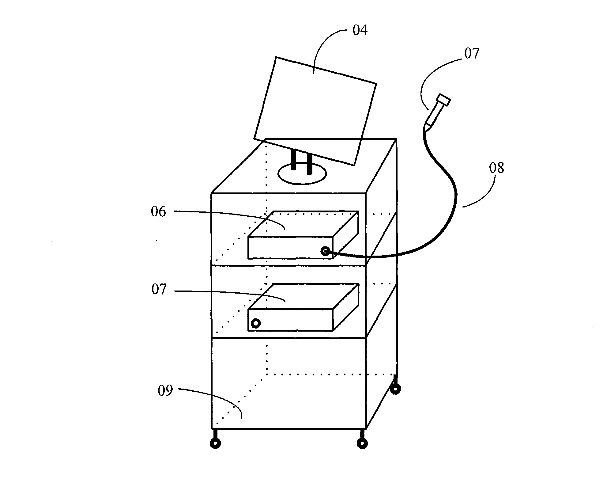
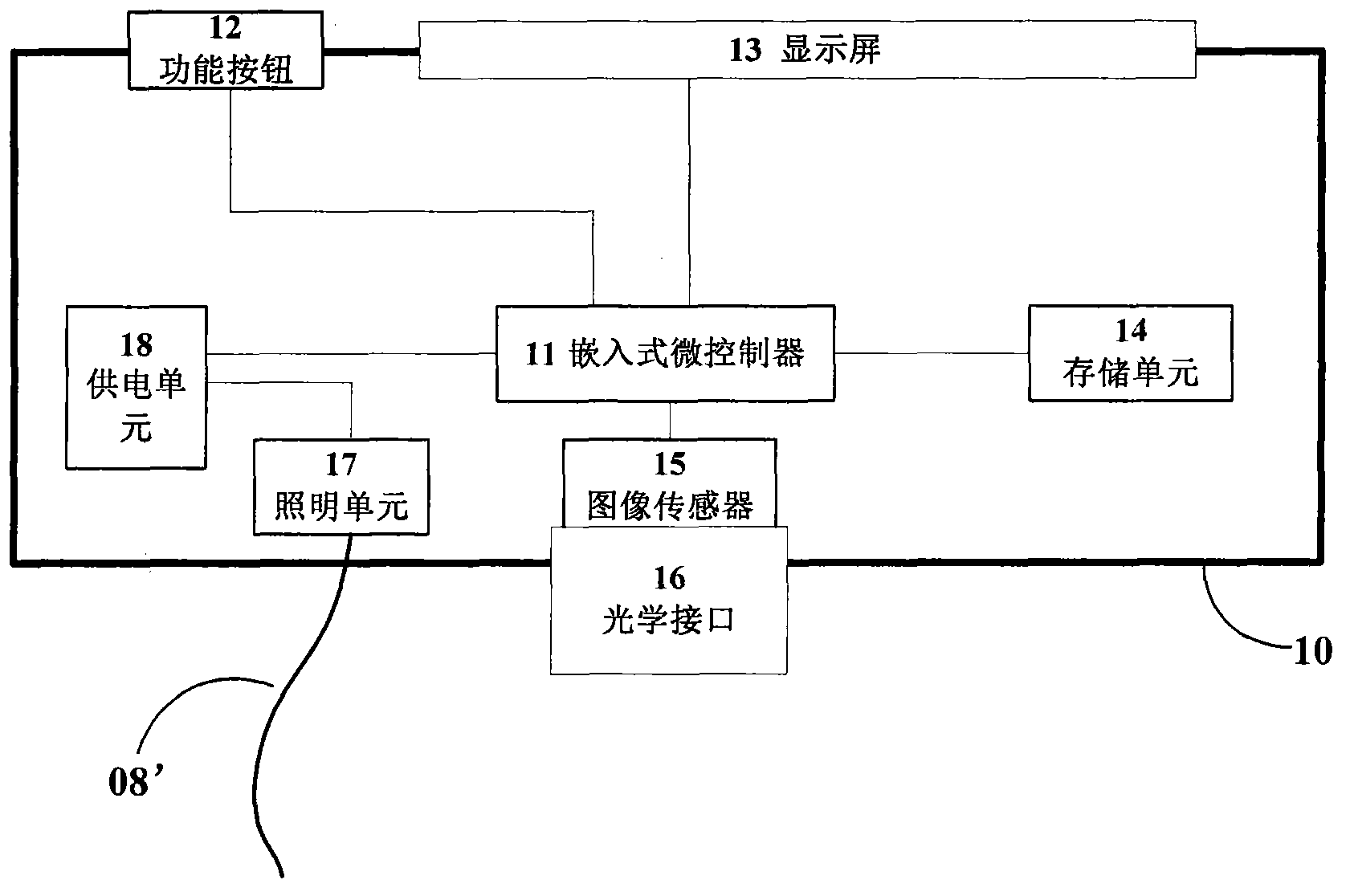
[0056] as attached image 3As shown, the video equipment of the present invention is a handheld video equipment as a whole, including a housing 10, and an embedded microcontroller 11, a storage unit 14, an image sensor 15, a lighting unit 17 and a power supply arranged in the cavity of the housing. unit 18, and a display screen 13, an optical interface 16 and function buttons 12 arranged on the panel of the casing. The storage unit 14, the image sensor 15, the display screen 13 and the function button 12 are all electrically connected to the embedded microcontroller 11, one end of the optical interface 16 is engaged with the housing 10, and is coaxially aligned with the image sensor 15, and the optical interface 16 The other end is used to engage the eyepiece part 03 of the endoscope, and the lighting unit 17 is connected to the light source interface of the endoscope through a light guide fiber 08'. The front structure of the handheld video equipment product is as follows ...
Embodiment 2
[0061] The structure of this embodiment is basically the same as that of Embodiment 1, the difference is that the lighting unit 17 is arranged outside the casing, and is directly engaged with the light source interface 02 of the endoscope, as shown in Figure 7 As shown, the lighting unit 17 is connected to the power supply unit 18 through a power line. In this embodiment, by extending the power line of the lighting unit, the lighting unit is arranged outside the casing and can be directly engaged with the light source interface of the endoscope to provide a light source for the endoscope, then the lighting unit of the video equipment and the endoscope There is no need for optical fiber between the light source interfaces, there is no light loss at all, and the utilization rate of the light source is improved.
Embodiment 3
[0063] As an improvement to Embodiment 1 or Embodiment 2, the handheld video device provided in this embodiment further includes a wireless sending unit 19 disposed in the housing for sending image data signals to an external display device. When the endoscope is actually used, in addition to the doctor holding the video device, in some cases, other cooperating doctors or nurses need to simultaneously view the images peeped by the endoscope. The video device provided in this embodiment has a built-in wireless transmission The unit 19 can wirelessly transmit the image data captured by the image sensor 15 to an external large-screen display device in real time. The wireless transmission module 19 is preferably a WIFI wireless transmission module, and the external large-screen display device can be a large-screen LED display with WIFI, or a projection curtain wall, etc.
PUM
 Abstract
Description
Claims
Application Information
 - R&D
- Intellectual Property
- Life Sciences
- Materials
- Tech Scout
- Unparalleled Data Quality
- Higher Quality Content
- 60% Fewer Hallucinations
Browse by: Latest US Patents, China's latest patents, Technical Efficacy Thesaurus, Application Domain, Technology Topic, Popular Technical Reports.
© 2025 PatSnap. All rights reserved.Legal|Privacy policy|Modern Slavery Act Transparency Statement|Sitemap|About US| Contact US: help@patsnap.com