Particle surface treating plant

A technology for processing equipment and particle surfaces, which is applied in chemical/physical processes, chemical instruments and methods, etc., can solve the problem of demanding particle properties, low universal applicability of particle fluidization, uneven contact time of particles of various particle sizes, etc. problem, to achieve the effect of stability, easy control, enhanced dispersion, and large axial space

Inactive Publication Date: 2014-03-26
刘东升
View PDF2 Cites 0 Cited by
  • Summary
  • Abstract
  • Description
  • Claims
  • Application Information

AI Technical Summary

Problems solved by technology

The fluidized bed is the most commonly used equipment for the surface treatment of gas particles and is widely used. However, the general fluidized bed has the following problems: First, the particle size is too small, the particles are easy to escape the fluidized chamber with the gas, and the particle treatment time is not easy. Second, the particle size distribution of the feed particles is too wide, and the contact time between particles of various particle sizes and the gas in the fluidization chamber is not uniform, resulting in poor particle surface treatment; third, the fluidized bed has strict requirements on particle properties. The fluidization properties of different material particles have different requirements on the fluidized bed. Therefore, it is difficult to grasp the fluidization properties of different material particles in the fluidized bed. Therefore, the universality of particle fluidization in fluidized bed equipment is not high; the fourth , the fluidized bed has restrictions on the industrialization of particle surface treatment. The surface treatment of industrialized material particles requires a large amount and is practical, while the general industrialized particle treatment involves particles of various particle sizes and materials; fifth, due to the fluidized bed The complexity of the structure, the dispersion of particles in the fluidized bed is generally difficult to solve

Method used


Image

  • Particle surface treating plant
  • Particle surface treating plant
  • Particle surface treating plant

Examples


Embodiment Construction

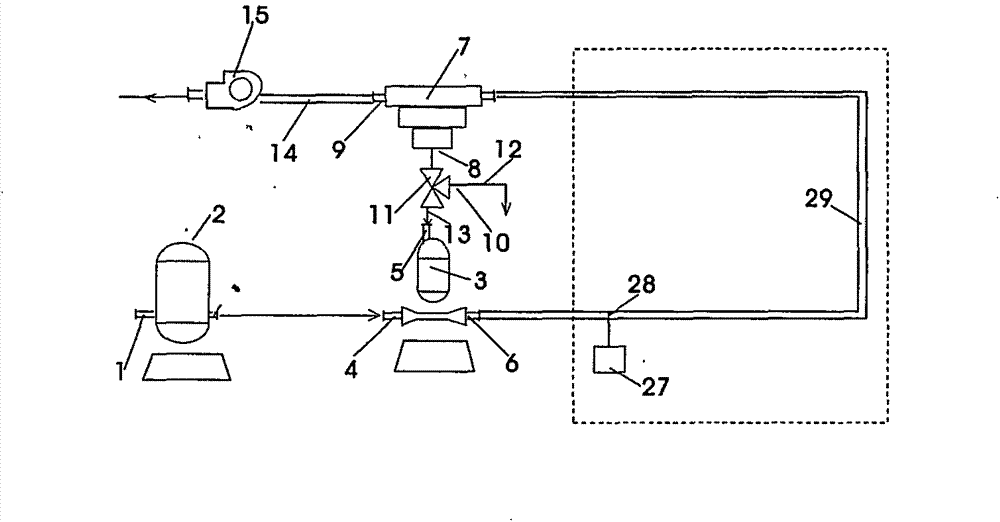
[0022] Such as figure 1 Shown is the first principle diagram of the pressure-feeding particle surface treatment equipment according to the present invention. The pressure-feeding pneumatic conveying system of material circulation is used as the particle fluidization equipment, and the particle is fluidized and surface treated by this equipment. It includes an air supply device 2 , a feeding device 3 , a delivery pipeline between the feeding device 3 and a discharge device 7 , a discharge device 7 , and an exhaust pipe 14 . Wherein, the feeding device 3 has a first gas inlet 4 and a second solid particle inlet 5, the first gas inlet 4 of the feeding device is connected with the gas supply device 2, and the outlet 6 of the feeding device is connected with the conveying pipeline, and the downstream of the conveying pipeline is Connected with the discharge device 7, the gas will be sent into the feed device 3 and the downstream conveying pipeline accordingly; the second inlet 5 o...


PUM


Abstract

The invention relates to a particle surface treating plant. A material-circulation pressure-type pneumatic transport system is used as a particle fluidizer; and the particle fluidizer is utilized to perform fluidization and surface treatment on the particles. The particle surface treating plant comprises an air feeder, wherein the air feeder is connected with a material supply unit; the material supply unit is provided with a first air inlet and a second solid particle inlet; and the air feeder is connected with the first air inlet of the material supply unit. An outlet of the material supply unit is connected with a transport pipeline; the transport pipeline is provided with a vibrator and a grid; the downstream part of the transport pipeline is connected with a discharge device; and the discharge device is provided with an air outlet and a solid particle outlet. The solid particle outlet of the discharge device and the second solid particle inlet of the material supply unit form a channel through an unloading device, so that the material particles are thoroughly mixed in the circulation loop pipeline in the fluidized state.

Description

technical field [0001] The invention belongs to the field of chemical industry and medicine, and in particular relates to a particle surface treatment device. Background technique [0002] Air and liquid flow methods are available for particle surface treatment techniques. Due to the late dispersion, filtration and drying of liquid flow treatment, and the complicated process, the surface treatment of particles gradually adopts gas treatment, that is, the particles are suspended in the gas, and the gas reacts with the surface of the particles. The fluidized bed is the most commonly used equipment for the surface treatment of gas particles and is widely used. However, the general fluidized bed has the following problems: First, the particle size is too small, the particles are easy to escape the fluidized chamber with the gas, and the particle treatment time is not easy. Second, the particle size distribution of the feed material is too wide, and the contact time of particles...

Claims


Application Information

Patent Timeline
Patent Type & Authority Applications(China)
IPC IPC(8): B01J8/24
Inventor 不公告发明人
Owner 刘东升
Why Eureka
Try Eureka