Cyclonic air current suspension device

A suspension device and cyclone technology, applied in the direction of transportation and packaging, conveyor objects, furnaces, etc., can solve the problems of reducing stress, reducing the suspension height of workpieces, and high cost of porous materials, and achieve the effect of increasing the suspension height

Active Publication Date: 2014-03-26
ZHEJIANG UNIV
View PDF7 Cites 5 Cited by
  • Summary
  • Abstract
  • Description
  • Claims
  • Application Information

AI Technical Summary

Problems solved by technology

Their difference lies in: small hole type ( Figure 2a ) directly sprays the airflow from the front to the workpiece, which will cause a large stress on the center of the workpiece; the porous material type ( Figure 2b ) can evenly flow compressed air at a low speed, avoiding the formation of pressure peaks and local stress concentration, but the porous material is expensive and difficult to maintain; Figure 2c and 2d It uses cyclone flow to form an air levitation device (the application publication number is CN102083720A, "vortex forming body and non-contact conveying device"). This element avoids direct jetting of airflow from the front to the workpiece by tangentially setting the air outlet, so it can Effectively reduce the stress acting on the workpiece; however, its disadvantage is: the negative pressure formed by the eddy current exerts an adsorption force on the workpiece, and the pulling effect of the adsorption force on the workpiece will reduce the suspension height of the workpiece, and, when the front end of the workpiece When entering a cyclonic flow area, the front end of the workpiece will be absorbed by the negative pressure, resulting in a significant reduction in the suspension height of the front end of the workpiece; Under the adsorption and pulling action of pressure, there will be a safety hazard of touching the air suspension device (see image 3 )
In order to increase the suspension height, we must increase the thickness of the air film flowing between the glass substrate and the air track; usually, we increase the thickness of the flowing air film by increasing the supply flow of air; however, increasing the supply flow of air will undoubtedly Increase the operating cost of the air levitation device and the production cost of the glass substrate

Method used


Image

  • Cyclonic air current suspension device
  • Cyclonic air current suspension device
  • Cyclonic air current suspension device

Examples


Embodiment Construction

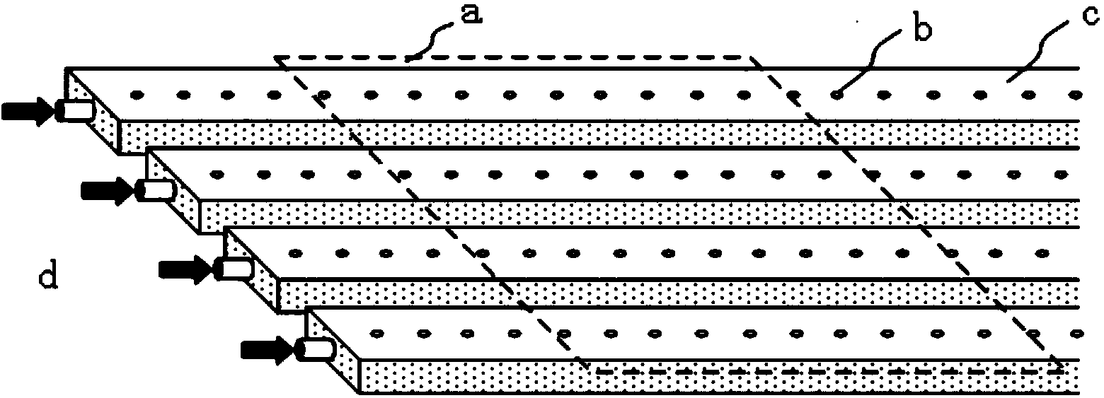
[0031] refer to Figure 4a to Figure 9, a cyclonic flow suspension device, including a suspension plane 1, the suspension plane 1 is provided with an inwardly concave swirl cavity 2 that generates negative pressure through a gas swirl, and the cross section of the swirl cavity 2 is circular, The bottom of the swirl chamber has a through hole 3 connected to the atmosphere, the through hole 3 is located in the center of the swirl chamber 2, and the diameter of the through hole 3 is smaller than the bottom diameter of the swirl chamber 2; the swirl chamber 2 and The compressed air supply source is connected, and the compressed air supply source is connected to the nozzle 4 on the wall surface of the swirl chamber, and the nozzle 4 faces the tangential direction of the wall surface of the swirl chamber; the swirl flow in the swirl chamber 2 forms a center The negative pressure inhales airflow from the through hole to increase the air volume supporting the suspension of the workpie...


PUM


Abstract

The invention discloses a cyclonic air current suspension device which comprises a suspension plane. The suspension plane is provided with an inward-concave swirl cavity which generates negative pressure through air cyclone, the cross section of the swirl cavity is circular, a through hole which is communicated with the atmosphere is formed in the bottom of the swirl cavity, the through hole is placed in the center of the swirl cavity, and the diameter of the through hole is smaller than the diameter of the bottom of the swirl cavity. The swirl cavity is connected with a compressed air supply air source which is connected with a nozzle in the wall face of the swirl cavity, and the nozzle faces the tangent line direction of the wall face of the swirl cavity. Rotational flow in the swirl cavity forms center negative pressure and sucks air flow from the through hole to be used for increasing the air flow for supporting workpieces to be suspended. Meanwhile, the sucked air flow can lower the negative pressure at the center so as to weaken the downward pulling effect of the negative pressure on the workpieces. Accordingly, the suspension height of the workpieces can be increased by forming the through hole in the center of the swirl cavity.

Description

technical field [0001] The invention relates to a cyclone flow suspension device. Background technique [0002] Flat panel display technology and its products represented by liquid crystal substrate displays and smart touch-screen mobile phones are widely used in our daily production and life. There are many processes and various testing links in the manufacturing process of flat panel display glass substrates (hereinafter referred to as "glass substrates"). The switching of each process and detection link makes the glass substrate frequently move between each workbench and the workshop. How to achieve safe, low-injury, and high-speed transmission and handling of glass substrates is a very critical large-scale manufacturing and assembly technology, and it is a key link to ensure production efficiency and yield. On the one hand, with the development of glass substrates in the direction of large size and thinning (for example, the length and width of the 10th generation glas...

Claims


Application Information

Patent Timeline
Patent Type & Authority Applications(China)
IPC IPC(8): B65G49/06B65G51/01
Inventor 黎鑫
Owner ZHEJIANG UNIV
Why Eureka
Try Eureka