Electronic biosensor based on single electric charge detection

An electronic sensor and base technology, applied in the field of electronic sensors, can solve problems such as harmful signal noise and achieve the effect of high sensitivity

Active Publication Date: 2014-03-26
南通康卓生物科技有限公司
View PDF3 Cites 17 Cited by
  • Summary
  • Abstract
  • Description
  • Claims
  • Application Information

AI Technical Summary

Problems solved by technology

This extra wiring can intr

Method used


Image

  • Electronic biosensor based on single electric charge detection
  • Electronic biosensor based on single electric charge detection

Examples


Example Embodiment

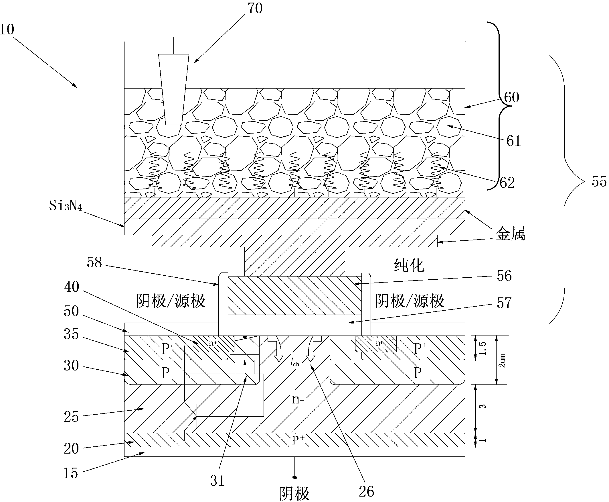
[0021] The electronic sensor 10 according to the present invention figure 1 It is schematically shown in, the electronic sensor includes a combined MOSFET and BJT, as shown in the schematic circuit diagram superimposed in the figure. reference figure 1 Starting from the bottom, the sensor device includes a silicon substrate as an anode layer 15 of a conventional type. The substrate 15 is preferably (100)-crystalline orientation. In the second embodiment of the present invention, the substrate 15 may also be a silicon-on-insulator (SOI) substrate. The substrate 15 may also be a SiC or Ge substrate. On the top of the anode 15, a vertical pnp transistor (Bipolar Junction Transistor-BJT) is formed by the following parts: the first p+ layer 20, which has a typical thickness of about 1 μm and a typical dopant concentration of 3×10 19 cm -3 ; N-region 25, its typical thickness is about 3μm and the typical dopant concentration is 10 16 cm -3 ; P zone 30, its typical surface concentrat...


PUM


Abstract

The invention relates to an electronic biosensor based on single electric charge detection; the invention discloses an electronic sensor of an ion-gated bipolar amplifier (IGBA); the electronic sensor comprises a combined type MOSFET, a BJT and a sample container connected with a floating gate electrode layer of the MOSFET; the electronic sensor has very high sensitivity, and can be used in solution ion detection, biology molecular detection and gas detection.

Description

technical field [0001] The present invention relates to electronic sensors capable of single charge detection. More specifically, the present invention relates to electronic biosensors based on ion-gated bipolar amplifiers. Background technique [0002] Point-of-care (POC) medical diagnostics present a huge market opportunity and significant socioeconomic impact. Specifically, especially in the context of personalized medicine, specific DNA and protein markers can be used for early diagnosis of cancer, cardiovascular diseases, infections or allergies, etc. For various reasons, testing for these markers is often cumbersome, expensive and requires highly specialized laboratories. At present, the methods for identifying and detecting specific biomolecules still have serious obstacles in terms of convenience, specificity, sensitivity, parallel processing, and cost reduction. At the same time, current state-of-the-art detection systems also require an extremely large amount of...

Claims


Application Information

Patent Timeline
IPC IPC(8): G01N27/48
Inventor 张世理汉斯.诺斯特罗姆沃尔夫.斯密思吴东平
Owner 南通康卓生物科技有限公司
Why Eureka
Try Eureka