Spaceflight optical remote sensing imaging simulation method based on space-time unified feature

An optical remote sensor and simulation method technology, applied in the field of aerospace optical remote sensing, can solve the problems that have not yet been discovered, do not involve imaging link signal, noise and MTF simulation, cannot realize on-orbit image simulation, etc., so as to improve imaging quality and ensure The effect of accuracy

Active Publication Date: 2014-03-26
BEIJING RES INST OF SPATIAL MECHANICAL & ELECTRICAL TECH
View PDF4 Cites 24 Cited by
  • Summary
  • Abstract
  • Description
  • Claims
  • Application Information

AI Technical Summary

Problems solved by technology

In the 14th issue of "Journal of System Simulation" in 2008, Zhang Dongying from the Anhui Institute of Optics and Fine Mechanics of the Chinese Academy of Sciences published the article "Simulation of Aerospace Optical Remote Sensor Imaging Based on Aerial Images", which established a system from aerial remote sensing images to aerospace remote sensing images. simulation model, but this method cannot realize the on-orbit image simulation under the condition of consistent changes in time and space in different latitude and longitude regions
[0005] Both of the above two articles only established a mathematical simulation model from the target to the remote sensor, and completed the signal simulation, but did not involve the signal, noise and MTF simulation of the entire imaging link
No related literature reports have been found so far

Method used


Image

  • Spaceflight optical remote sensing imaging simulation method based on space-time unified feature
  • Spaceflight optical remote sensing imaging simulation method based on space-time unified feature
  • Spaceflight optical remote sensing imaging simulation method based on space-time unified feature

Examples


Embodiment Construction

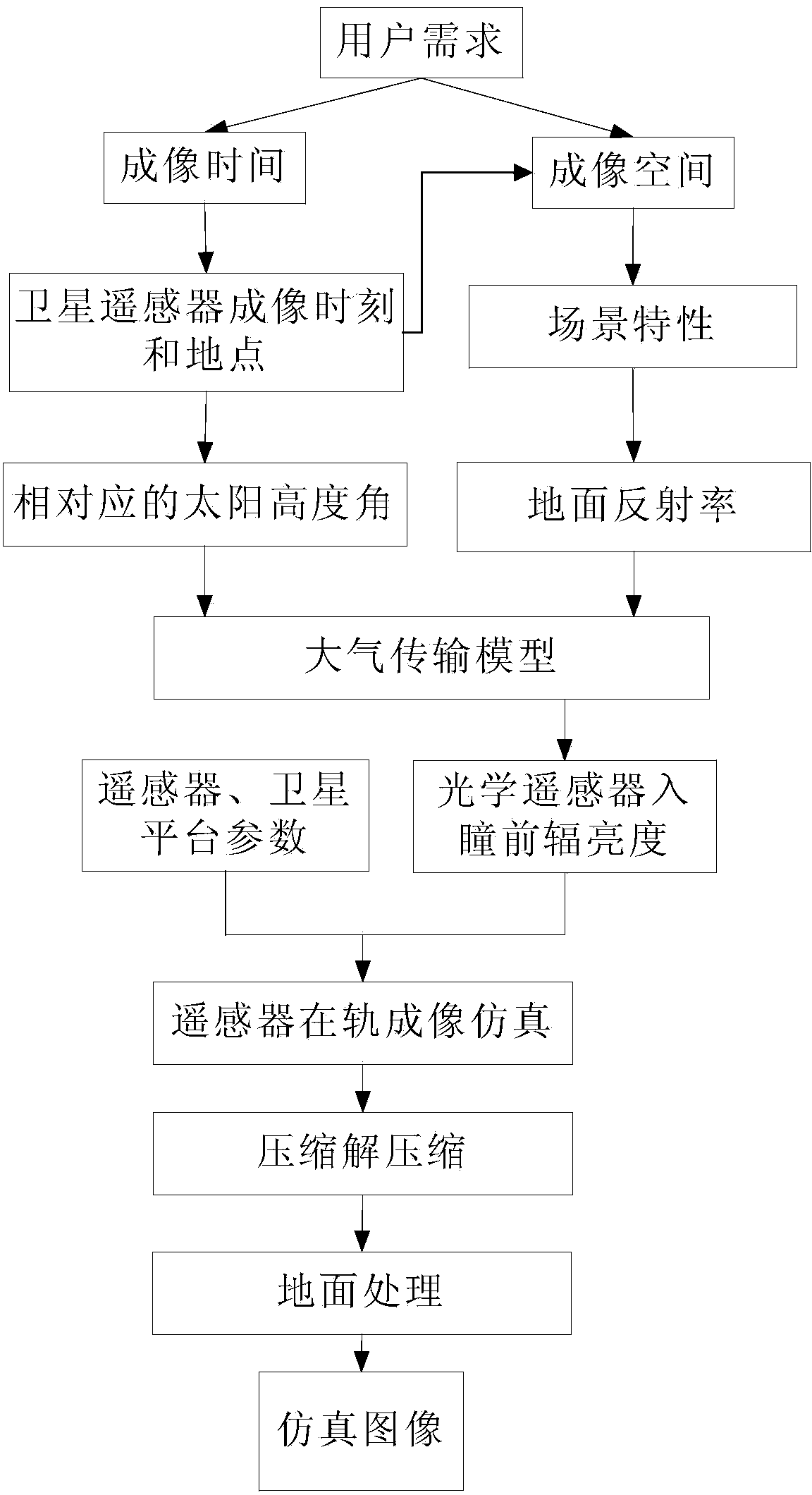
[0031] like figure 1 As shown, it is the specific implementation way of the method of the present invention.

[0032] (1) Determination of satellite orbit parameters:

[0033] First, according to user needs, set six numbers of satellite orbits: true perigee angle, argument of perigee, orbital inclination, ascending node right ascension, eccentricity and orbital semi-major axis to determine the orbit of the satellite after it goes to the sky.

[0034] Before calculating the satellite orbit parameters, we must first introduce the two coordinate systems used: the geocentric orbit coordinate system and the equatorial inertial coordinate system.

[0035] The geocentric orbital coordinate system is: the origin O is at the center of the earth, x 0 The axis points from the center of the earth to the spacecraft, that is, along the distance vector r, y from the center of the earth 0 The axis is in the orbital plane, perpendicular to the vector r, pointing forward, z 0 The axes are p...


PUM


Abstract

A spaceflight optical remote sensing imaging simulation method based on a space-time unified feature comprises the steps that (1), the relation of the position of a satellite at any GMT and the time and the longitude and latitude of the satellite at a GMT sub-satellite point are obtained in a calculating mode according to satellite orbit parameters; (2), the entrance pupil radiance L (lamda) of a remote sensor is obtained in a calculating mode according to the longitude and latitude of the satellite at the GMT sub-satellite point, an imaging time ground target reflectivity feature pho and a solar elevation angle theta; (3), the signal Starget of the remote sensor is obtained by combining the remote senor parameters and L (lamda), linear amplification, smoothing and quantization processing are carried out on the Starget in sequence, and an initial simulation image is obtained after a remote sensor optical system, a remote sensor detector, a remote sensor circuit and a simulation MTF of a satellite platform are overlaid; (4), after compression, uncompression, radiation correction and MTF compensation are carried out on the initial simulation image, a simulation image needed by a user is obtained. The method can carry out effective optical remote sensing full-chain imaging simulation, and optical remote sensing in-orbit imaging quality is greatly improved.

Description

technical field [0001] The invention belongs to the technical field of aerospace optical remote sensing, and relates to a method for simulating imaging of an aerospace optical remote sensor on the ground. Background technique [0002] Optical remote sensing image quality is a key parameter to evaluate the quality of remote sensing data and the imaging capability of remote sensors. With the urgent demand for high-resolution satellites, the quality of optical remote sensing images is becoming more and more important to users, and image quality has become one of the important evaluation indicators for the development of space optical cameras. The scientific and rational design of the parameters of the remote sensor has become the core task in the early stage of the development of the remote sensor, and it is the key to ensure the final acquisition of high-quality images in orbit. [0003] The design of the current optical remote sensor signal-to-noise ratio is based on the sig...

Claims


Application Information

Patent Timeline
Patent Type & Authority Applications(China)
IPC IPC(8): G01S7/497
CPCG01S7/497
Inventor 鲍云飞何红艳阮宁娟王殿中邢坤周楠岳春宇李岩李方琦齐文霁
Owner BEIJING RES INST OF SPATIAL MECHANICAL & ELECTRICAL TECH
Why Eureka
Try Eureka