Optical fiber for increasing spatial divergence angle of outputted light beam and homogenizing light spot and application thereof

A divergence angle, optical fiber technology, applied in the direction of coupling of optical waveguides, can solve problems such as reducing the flexibility of laser placement

Active Publication Date: 2014-03-26
Shandong Huaguang Optoelectronics Co. Ltd.
View PDF10 Cites 7 Cited by
  • Summary
  • Abstract
  • Description
  • Claims
  • Application Information

AI Technical Summary

Problems solved by technology

In this method, adding mixed-mode materials in the optical fiber protection sleeve increases the diameter of the sleeve, and the hardness o

Method used


Image

  • Optical fiber for increasing spatial divergence angle of outputted light beam and homogenizing light spot and application thereof
  • Optical fiber for increasing spatial divergence angle of outputted light beam and homogenizing light spot and application thereof
  • Optical fiber for increasing spatial divergence angle of outputted light beam and homogenizing light spot and application thereof

Examples


Embodiment 1

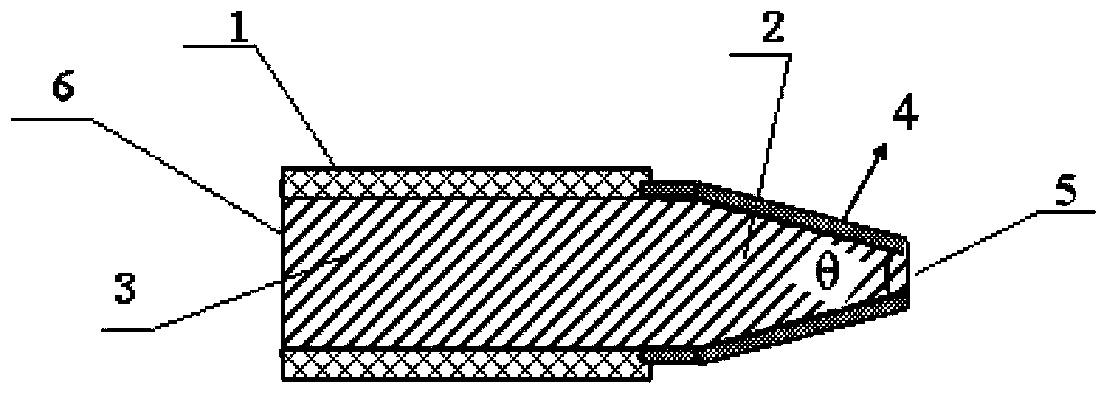
[0032] An optical fiber for increasing the spatial divergence angle of the output beam and homogenizing the spot, comprising a cylindrical optical fiber main body 3, an optical fiber coating layer 1 is arranged on the surface of the cylindrical optical fiber main body 3, and one end of the optical fiber main body 3 has a tapered optical fiber structure 2. The ratio of the area of ​​the end face 5 of the tapered optical fiber structure to the area of ​​the cross section 6 of the cylindrical optical fiber body is 1:1.5, and a layer of high reflection film 4 is plated on the sector surface of the tapered optical fiber structure 2. The high reflection film 4 is a 650 nm high reflection film.

[0033] The taper angle θ of the tapered fiber structure 2 is 20°. The diameter of the cylindrical optical fiber body 3: 308 μm.

Embodiment 2

[0035] A method for homogenizing a spot of a light beam by using the optical fiber described in embodiment 1, including the following steps:

[0036] (1) Pass the optical fiber into the protective tube, expose the tapered optical fiber structure 2 at one end of the protective tube, and expose a section of cylindrical optical fiber body 3 at the other end of the protective tube;

[0037] (2) Pass the exposed cylindrical optical fiber body 3 through the glue-filled connector to expose the part;

[0038] (3) Curing the glue in the connector;

[0039] (4) After curing, the cylindrical fiber body 3 exposed outside the connector is removed to form the fiber end face, and the fiber end face is polished to obtain an optical plane perpendicular to the central axis of the fiber to make an optical fiber jumper. Structure 2 is the output end of the optical fiber jumper, and the connector is the connection end of the optical fiber jumper;

[0040] (5) When in use, connect the connector of the above...

Embodiment 3

[0049] The optical fiber for increasing the spatial divergence angle of the output beam and homogenizing the spot as described in embodiment 1, the difference is that the area ratio of the end surface 5 of the tapered optical fiber structure to the cross section 6 of the cylindrical optical fiber body is: 1:2, a high-reflection film 4 is plated on the sector surface of the tapered optical fiber structure. The high reflective film is a 808 nm high reflective film 4.

[0050] The tapered angle θ of the tapered optical fiber structure 2 is 35°. The diameter of the cylindrical optical fiber body 3: 440 μm.

[0051] The optical fiber jumper prepared by this embodiment transmits light beams compared to ordinary optical fibers, and its beam quality factor is M 2 Decrease by 71%, increase brightness by 6 times, and homogenize light spots.


PUM

PropertyMeasurementUnit
Diameteraaaaaaaaaa
Diameteraaaaaaaaaa
Diameteraaaaaaaaaa

Abstract

The invention provides an optical fiber for increasing a spatial divergence angle of an outputted light beam and homogenizing light spots. The optical fiber comprises a cylindrical optical fiber body the surface of which is equipped with a fiber coating. One end of the optical fiber body is configured in a taper optical fiber structure. The ratio of the end face area of the taper optical fiber structure to the cross sectional area of the cylindrical optical fiber body is between 1 to 1.1 and 1 to 2. The scalloped surface of the taper optical fiber structure is plated with a high-reflective film. One end of the optical fiber configured in a taper structure and the scalloped surface of the taper structure is plated with the high-reflective film. Thus, part of light beam in the optical fiber is continuously reflected along the high-reflective film on the surface of the taper structure in order to increase the divergence angle of the light beam. Therefore, the aggregating effect of the light spots is further dispersed, namely, a purpose of homogenizing light spots is achieved. In addition, light beam mode mixture is achieved.

Description

Technical field [0001] The invention relates to an optical fiber for increasing the spatial divergence angle and homogenization of the output beam and its application, and belongs to the technical field of optical fiber optics. Background technique [0002] Fiber-coupled semiconductor lasers have flexibility in use and are widely used in semiconductor laser pumping solid-state lasers, laser cutting, laser lighting, laser marking, laser printing and other fields. The field of laser night vision and lighting requires the beam to have a large spatial divergence angle, and the spatial distribution of the beam is symmetrical and uniform. However, because the laser has high directivity and is limited by the numerical aperture of the output fiber, the beam divergence angle is limited, which limits the irradiation area of ​​the light source. At the same time, because the fiber used in the high-power laser is a multi-mode fiber, there are multiple high-order mode distribution forms durin...

Claims


Application Information

Patent Timeline
IPC IPC(8): G02B6/42
Inventor 刘成成于果蕾秦华兵江建民
Owner Shandong Huaguang Optoelectronics Co. Ltd.
Why Eureka
Try Eureka