High-precision method and device for measuring interval between positive time and negative time

A technology of time interval measurement and time interval, which is applied in the direction of electrical unknown time interval measurement, devices and instruments for measuring time interval, etc. It can solve the problem of reducing the measurement accuracy of positive and negative time intervals, the inability to realize the measurement gate extraction circuit, and high time interval Problems such as measurement accuracy, to achieve the effect of wide positive and negative time interval measurement range, simple design, and high time interval measurement resolution

Active Publication Date: 2014-03-26
THE 41ST INST OF CHINA ELECTRONICS TECH GRP
View PDF4 Cites 51 Cited by
  • Summary
  • Abstract
  • Description
  • Claims
  • Application Information

AI Technical Summary

Problems solved by technology

[0006] 1. When a single channel is used to measure the positive and negative time intervals, when two events occur very close to each other, for example, when the time interval is less than 50ps, it is difficult to judge which event is ahead and which event is late based on the response speed of the current device , there will be a dead zone in the polarity detection during positive and negative time interval measurement, which will reduce the accuracy o

Method used


Image

  • High-precision method and device for measuring interval between positive time and negative time
  • High-precision method and device for measuring interval between positive time and negative time
  • High-precision method and device for measuring interval between positive time and negative time

Examples


Embodiment 1

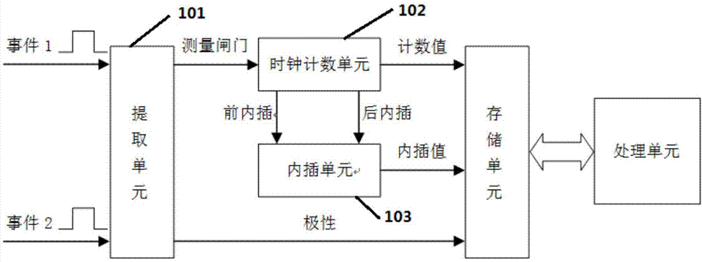
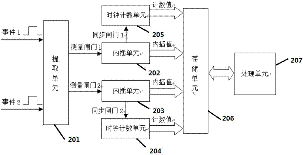
[0030] Such as Figure 3-8 As shown, the positive and negative time interval measuring device of the present invention comprises the following parts:

[0031] The signal shaping and measurement gate extraction unit compares and shapes the input signal according to the set trigger level, converts the measured signal into an ECL signal for subsequent processing, and uses the trigger to extract the two gate signals that need to be measured.

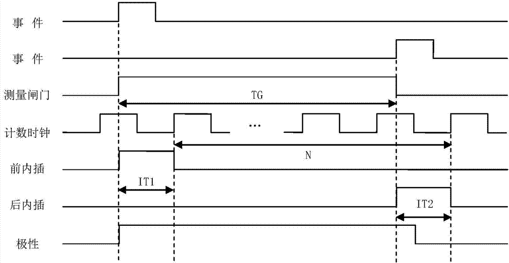
[0032] The synchronization and interpolation unit uses the counting clock to sample the measurement gate signal to obtain a gate signal synchronized with the counting clock. One route is sent to the clock counting unit for rough measurement of the measurement gate, and the other route is sent to the interpolation unit for pre-interpolation measurement. Accurate measurement of the fraction of a clock cycle less than the leading edge of the measurement gate.

[0033] The clock counting unit uses the synchronous gate signal to control the coun...

Embodiment 2

[0051] On the basis of the foregoing embodiments, the method provided in this embodiment is:

[0052] Step 1: Set the comparison level according to the peak value and valley value of the input signal, and convert the input signal into an ECL signal through a high-speed comparator, so that it has a smaller rising and falling edge time to reduce the trigger error.

[0053] Step 2: Send the ECL signal shaped by the high-speed comparator to the clock port of the D-type flip-flop. The data terminal of the D-type flip-flop is connected to a high level. After a rising edge, the flip-flop output is high immediately.

[0054] Step 3: Send the inverting output signals of the two D-type flip-flops to the FPGA. After the FPGA detects that both signals are low, after a period of delay, it resets the two flip-flops at the same time, and the output of the two flip-flops The signal is forced low so that the two flip-flop outputs form a pulse signal. The positive-phase output signal of the tr...


PUM


Abstract

The invention provides a high-precision method and device for measuring an interval between positive time and negative time. The device comprises a signal shaping and measuring gate extracting unit, a synchronization and interpolation unit, a clock counting unit, a storage unit and a data processing unit, wherein the signal shaping and measuring gate extracting unit, the synchronization and interpolation unit, the clock counting unit, the storage unit and the data processing unit are in connection with one another and in communication with one another. The signal shaping and measuring gate extracting unit conducts comparing and shaping on input signals according to a trigger level, converts measured signals into ECL level signals, and extracts gate signals corresponding to the measured signals through an ECL trigger. The synchronization and interpolation unit samples the two routes of gate signals through a counting clock. By means of the scheme, various types of signal input can be achieved, and the wide input dynamic range can be supported; a channel circuit is obtained through a high-speed ECL device, the channel bandwidth is large, narrow-pulse measurement can be achieved, the minimum measurable pulse width can reach 2.5ns, and the measurement resolution ratio can reach 40ps.

Description

technical field [0001] The invention belongs to the technical field of positive and negative time interval measurement, and in particular relates to a high-precision positive and negative time interval measurement method and device. Background technique [0002] High-precision time interval measurement technology is widely used in satellite navigation, radar positioning, laser ranging, nuclear physics detection and time-frequency measurement and other fields. The National Academy of Sciences of the United States regards it as one of the important symbols for evaluating national defense strength, holds precision time and time interval measurement technology exchange meetings every year, and regards it as one of the science and technology that the country must vigorously develop. Currently widely used time interval measurement methods include pulse counting method, analog interpolation method, delay line interpolation method, vernier method and time-amplitude conversion method...

Claims


Application Information

Patent Timeline
IPC IPC(8): G04F10/04
Inventor 刘朱伟杜念文毛黎明白轶容蒙海瑛
Owner THE 41ST INST OF CHINA ELECTRONICS TECH GRP
Why Eureka
Try Eureka