
Multi-node automatic memory allocation method based on reflective memory network

A reflective memory network and automatic allocation technology, applied in resource allocation, multi-programming devices, electrical components, etc., can solve the problems of rigid memory allocation, poor networking flexibility, and large workload, and achieve the effect of easy management and query

Inactive Publication Date: 2014-03-26
CHINA ACADEMY OF SPACE TECHNOLOGY
View PDF5 Cites 8 Cited by
  • Summary
  • Abstract
  • Description
  • Claims
  • Application Information

AI Technical Summary

Problems solved by technology

The existing reflective node network memory allocation method is mainly to pre-allocate fixed addresses for all data variables that need to use memory space for each node by calculating the number of predetermined network nodes and the data requirements of each node ("Real-time Network System Design Based on Reflective Memory", Lin Xiaohuan, Journal of Xi’an Polytechnic University, Vol. 24, No. 1), this method has poor networking flexibility and rigid memory allocation. If a node in the network joins or exits, or any node in the network has a variable increase, it is necessary to manually reset the memory Address calculation and space allocation to prevent pointer out-of-bounds and array overflow due to unreasonable memory allocation
Especially when there are many nodes connected in the network, the number of nodes in the network and the changes of variables on each node will bring a large workload

Method used


Image

  • Multi-node automatic memory allocation method based on reflective memory network
  • Multi-node automatic memory allocation method based on reflective memory network
  • Multi-node automatic memory allocation method based on reflective memory network

Examples


Embodiment

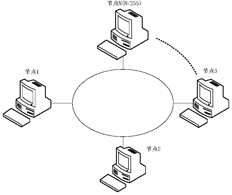
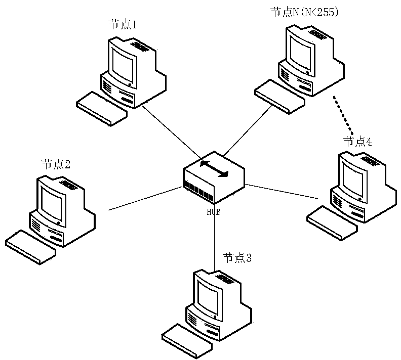
[0038] Select three reflective memory node cards and load them into the computer, and use optical fibers to form a reflective memory network as shown in Figure 1; the node numbers of the three node cards are set to 0x01, 0x02 and 0x03 through jumpers respectively. The reflective memory node card selected here is VMIPCI-5565 produced by GE, and its main features are as follows:

[0039] The longest connection distance of multi-mode fiber is 300m, and the longest connection distance of single-mode fiber is 10km

[0040] ●Data packet size can be dynamically adjusted between 4-64 bytes

[0041] ●Transfer rate from 47.1MB / s (4-byte packet length) to 174MB / s (64-byte packet length)

[0042] ●128M reflective memory

[0043] ●Two independent DMA channels

[0044] ●Any node can send interrupt information to the specified node or all nodes

[0045] ●With error detection function

[0046] After the reflective memory network is formed, the node card startup process is carried out: fi...


PUM


Abstract

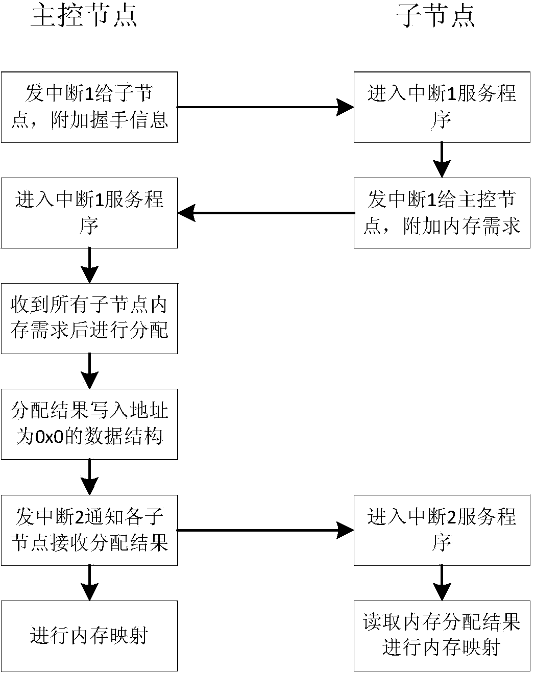
The invention discloses a multi-node automatic memory allocation method based on a reflective memory network. The method comprises the steps that the reflective memory network is established; (2) one node in the reflective memory network is appointed to be a master control node, all node data structures in the reflective memory network are defined in the master control node; (3) all nodes are started, and an interrupt 1 and an interrupt 2 of each node are made to play roles; (4) the master control node sends handshake information to other child nodes, connection is established between the master control node and the child nodes, and the child nodes receive the handshake information through the interrupt 1; (5) after the child nodes receive the handshake information, the memory data needed by the child nodes are returned to the master control node; (6) the master control node conducts statistics on the number of the child nodes in the reflective memory network, memory allocation of the reflective memory network is conducted uniformly, and memory allocation results are stored to local memories; (7) the master control node informs all the child nodes to read the memory allocation result in the respective local memory through the interrupt 2; the master control node and the child nodes respectively conduct memory pointer mapping according to the memory allocation results, and automatic memory allocation is achieved.

Description

technical field [0001] The invention relates to a multi-node memory allocation method in network communication, in particular to a multi-node memory allocation method based on a reflective memory network. Background technique [0002] Reflective Memory (RFM) network is a high-speed replication shared memory network that supports multi-computer systems with different bus structures and different types of operating systems to share high-speed, stable real-time data. Each computer connected to the network is equipped with an RFM node card. When the data is written into the memory of the node card of a counter, the node card automatically sends the data to other nodes in the network through the optical fiber in sequence. The same address in the memory of other node cards The above will write the same content as the sender, and each node in the network only needs to access the memory of the local node card when accessing data of other nodes. The operation is completely performed...

Claims


Application Information

Patent Timeline
IPC IPC(8): G06F9/50H04L29/08
Inventor 庞羽佳李志陈新龙陈大可韩旭朱孟萍
Owner CHINA ACADEMY OF SPACE TECHNOLOGY
Learn More