Intelligent traffic light control system of passive millimeter waves based on traffic flow
A control system and millimeter wave technology, applied in the control of traffic signals and other directions, can solve the problems of low detection accuracy, poor detection performance, electromagnetic pollution, etc., and achieve the effects of strong detection performance, improved detection performance, and convenient installation.
- Summary
- Abstract
- Description
- Claims
- Application Information
AI Technical Summary
Problems solved by technology
Method used
Image

Examples
specific Embodiment approach 1
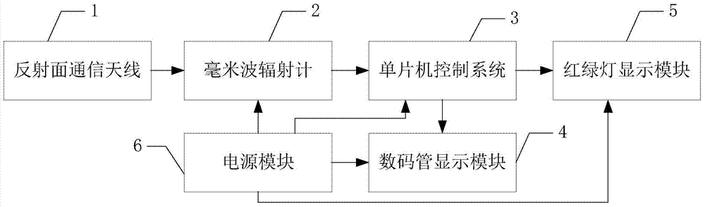
[0038] Specific implementation mode one: see figure 1 Describe this embodiment mode, a kind of passive millimeter-wave intelligent traffic light control system based on traffic flow described in this embodiment mode, it comprises reflective surface communication antenna 1, millimeter-wave radiometer 2, single-chip microcomputer control system 3, nixie tube display module 4 , a traffic light display module 5 and a power supply module 6;
[0039] The millimeter-wave signal output end of the reflective surface communication antenna 1 is connected to the millimeter-wave signal input end of the millimeter-wave radiometer 2, the voltage signal output end of the millimeter-wave radiometer 2 is connected to the voltage signal input end of the single-chip microcomputer control system 3, and the power supply The module 6 is used to provide working power for the millimeter wave radiometer 2, the single-chip microcomputer control system 3, the nixie tube display module 4 and the traffic ...
specific Embodiment approach 2
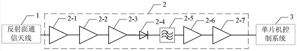
[0042] Specific implementation mode two: see figure 2 Describe this embodiment. The difference between this embodiment and the traffic flow-based passive millimeter-wave intelligent traffic light control system described in the first embodiment is that the millimeter-wave radiometer 2 includes a No. 1 high-frequency amplifier 2- 1, No. 2 high-frequency amplifier 2-2, No. 3 high-frequency amplifier 2-3, square detector 2-4, filter 2-5, No. 1 low-frequency amplifier 2-6 and No. 2 low-frequency amplifier 2-7,
[0043] The millimeter-wave signal input end of the No. 1 high-frequency amplifier 2-1 is the millimeter-wave signal input end of the millimeter-wave radiometer 2, and the millimeter-wave signal output end of the No. 1 high-frequency amplifier 2-1 is connected to the No. 2 high-frequency amplifier. The millimeter-wave signal input terminal of No. 2-2 is connected, the millimeter-wave signal output terminal of No. 2 high-frequency amplifier 2-2 is connected with the millime...
specific Embodiment approach 3
[0046] Specific implementation mode three: see figure 1 with 2 This embodiment is described. The difference between this embodiment and the traffic flow-based passive millimeter-wave intelligent traffic light control system described in Embodiment 1 or Embodiment 2 is that the single-chip microcomputer control system 3 is realized by AT89C51.
PUM
 Abstract
Description
Claims
Application Information
 - R&D
- Intellectual Property
- Life Sciences
- Materials
- Tech Scout
- Unparalleled Data Quality
- Higher Quality Content
- 60% Fewer Hallucinations
Browse by: Latest US Patents, China's latest patents, Technical Efficacy Thesaurus, Application Domain, Technology Topic, Popular Technical Reports.
© 2025 PatSnap. All rights reserved.Legal|Privacy policy|Modern Slavery Act Transparency Statement|Sitemap|About US| Contact US: help@patsnap.com