Stator permanent magnet biased permanent magnet type bearingless motor

A bearingless motor, permanent magnet bias technology, applied in synchronous motors with static armatures and rotating magnets, holding devices with magnetic attraction or thrust, electrical components, etc., can solve the problem of small radial suspension force and high precision Low, complex control and other problems, to achieve the effect of large radial suspension force and uniform air gap

Active Publication Date: 2014-03-26
淮安市清江浦区市场监管综合服务中心
View PDF5 Cites 20 Cited by
  • Summary
  • Abstract
  • Description
  • Claims
  • Application Information

AI Technical Summary

Problems solved by technology

When selecting the thickness of the permanent magnet of the rotor, it is necessary to comprehensively consider the mutual constraint relationship between the magnitude of the radial levitation force and the magnitude of the torque. Therefore, the generation of the radial levitation force is limited; There is strong coupling, and complex decoupling control strategies need to be used to decouple the rotation system and the suspension system, and the suspension force is closely related to the rotor position angle, so the existing permanent magnet bearingless motor has radial suspension force generated Disadvantages of smaller size, complex control and less precision

Method used


Image

  • Stator permanent magnet biased permanent magnet type bearingless motor
  • Stator permanent magnet biased permanent magnet type bearingless motor

Examples


Embodiment Construction

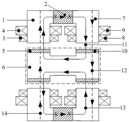
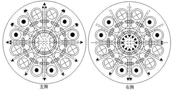
[0018] like figure 1 , 2 As shown, the present invention includes a motor housing, a rotor and a stator are arranged in the motor housing, and the stator includes a left stator core 1 and a right stator core 7, and a left stator core 1 and a right stator core 7 are provided with Axially magnetized annular stator permanent magnet 2, a torque winding 4 and a suspension winding 3 are arranged in the stator slot of the left stator core 1, a torque winding 9 and a suspension winding 8 are arranged in the stator slot of the right stator core 7, and the suspension winding 3. The suspension winding 8 is located in the inner layer of the stator slot, the torque winding 4 and the torque winding 9 are located in the outer layer of the stator slot; the rotor includes the rotor core 6, and the left side of the rotor core 6 is respectively provided with a radially magnetized left annular rotor permanent magnet 5. The right annular rotor permanent magnet 10 and the rotating shaft; the annul...


PUM


Abstract

The invention discloses a stator permanent magnet biased permanent magnet type bearingless motor which comprises a motor shell. A rotor and a stator are arranged in the motor shell, and the stator comprises a left stator core and a right stator core, an axial magnetized annular stator permanent magnet is arranged between the left stator core and the right stator core, a torque winding and a suspension winding are arranged in stator slots of the left stator core, a torque winding and a suspension winding are arranged in stator slots of the right stator core. The rotor comprises a rotor core, and a radial magnetized left annular rotor permanent magnet, a radial magnetized right annular rotor permanent magnet and a rotating shaft are respectively arranged on two sides of the rotor core. The stator permanent magnet biased permanent magnet type bearingless motor aims to overcome the shortcomings of an existing permanent magnet type bearingless motor, and the structure of the stator permanent magnet biased permanent magnet type bearingless motor is simple in control, realizes mutually independent suspension control and torque control, and can generate larger radial suspension force.

Description

[0001] technical field [0002] The invention relates to the technical field of motor equipment, in particular to a stator permanent magnet bias permanent magnet bearingless motor with simple control and greater radial levitation force. Background technique [0003] Bearingless motors have no friction and wear, no lubrication, and are easy to achieve higher speed and higher power operation, especially the permanent magnet bearingless motors have simple structure, high operating reliability, small size, light weight, high efficiency and With advantages such as high power density, it has broad application prospects in the fields of flywheel energy storage, high-speed machine tool spindle motors and sealed pumps, centrifuges, compressors, and high-speed micro hard disk drives. [0004] The existing permanent magnet type bearingless motor is superimposed on the torque winding of the stator slot of the traditional permanent magnet synchronous motor with an additional suspension f...

Claims


Application Information

Patent Timeline
Patent Type & Authority Applications(China)
IPC IPC(8): H02K21/14H02K1/17H02N15/00
Inventor 张涛倪伟张晨叶小婷丁卫红邬清海张惠萍
Owner 淮安市清江浦区市场监管综合服务中心
Why Eureka
Try Eureka