Machining method of cycloidal-tooth bevel gear

A technology of cycloidal bevel gear and processing method, which is applied in the direction of belt/chain/gear, gear teeth, components with teeth, etc., which can solve the problems of poor rigidity of machine tools, inability to directly specify the position of the contact area, complex structure, etc. , to achieve the effects of increased rigidity, simplified machine tool structure, and simplified cutterhead structure

Active Publication Date: 2014-04-02
TIANJIN TEEK TRANSMISSION
View PDF5 Cites 20 Cited by
  • Summary
  • Abstract
  • Description
  • Claims
  • Application Information

AI Technical Summary

Problems solved by technology

[0007] 1) Klingelnberg adopts a split cutter head. The inner and outer cutter teeth are respectively installed on two independent cutter bodies, which are embedded and stacked together. The eccentricity of the inner and outer cutter bodies is realized through the cross slider mechanism. The structure is extremely complicated and the design and processing are difficult.
The structure of the split cutter head and the cross slider leads to poor rigidity of the machine tool. At the same time, the split cutter head cannot perform high-speed dry cutting;
[0008] 2) Oerlikon adopts the tool tilting method to overcome the defect of "restraint", but the machine tool is equipped with a tool tilting tool rotation mechanism, the machine tool structure is complicated and the calculation and adjustment are complicated;
[0009] Both the traditional Klingelnberg and Oerlikon methods cannot directly specify the position of the contact area, and repeated trial cutting is required, and it is difficult to control the contact spots and motion curves of the gear pair

Method used


Image

  • Machining method of cycloidal-tooth bevel gear
  • Machining method of cycloidal-tooth bevel gear
  • Machining method of cycloidal-tooth bevel gear

Examples


Embodiment

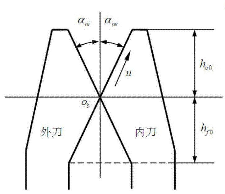
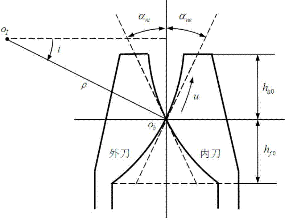
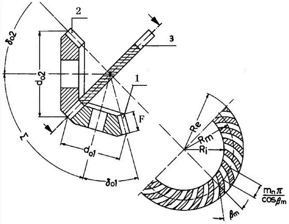
[0061] Embodiment: A pair of cycloidal hypoid gears were machined with the disc cutter according to the above method. Gear secondary shaft intersection angle Σ=90°, offset distance a v =25mm, number of gear teeth z 2 =39, the number of small wheel teeth z 1 =8, outer pitch circle diameter of big wheel d 02 =265mm, midpoint helix angle β m2 =34.63°, average pressure angle α n =21.5°, tooth width b 2 =40mm. Tool parameters (see Figure 4), cutterhead radius: r c =106.5mm, number of cutter head: z 0 =5, cutter tooth profile angle: small wheel inner cutter α ni =22°, small wheel outer knife α ne =20.5°; the big wheel cutter adopts a straight blade, and the pressure angle is opposite to that of the small wheel.

[0062] The specific implementation is as follows:

[0063] (1) Determine the basic parameters of the shape wheel

[0064]

[0065] Midpoint radius R m Equal to the midpoint taper distance of the gear pair

[0066]

[0067] The midpoint helix angle is equ...


PUM


Abstract

The invention discloses a machining method of a cycloidal-tooth bevel gear. The machining method comprises the following steps: (1) determining basic parameters of a generating wheel; (2) determining the movement for forming a tooth surface of the generating wheel; (3) determining the movement for expanding the generating wheel into the gear; (4) correcting the movement for expanding the generating wheel into the gear; and (5) finishing expansion of the machined gear. Compared with the Klingelnberg method, the machining method disclosed by the invention has the advantages that the structure of a tool disc is greatly simplified, a cross-shaped sliding block mechanism is not needed and the rigidity is improved; compared with the Oerlikon method, the machining method disclosed by the invention has the advantages that a tool inclining mechanism is not needed, so that the structure of a machine tool is greatly simplified and the rigidity is improved; the cycloidal-tooth bevel gear and a quasi-hyperbolic gear are processed on a bevel gear milling machine without a tool inclining and swinging disc; the correction of the tooth surface does not cause additional adjustment of the machine tool and the tool; second-order precontrol of the position, the size and the shape of contact spots of the tooth surface can be realized; second-order precontrol of required transfer errors can be realized; and a cycloidal-teeth bevel gear pair conjugate completely on theory also can be machined.

Description

Technical field: [0001] The invention relates to the field of spiral bevel gear processing, in particular to a cycloidal bevel gear processing method. Background technique: [0002] Cycloidal bevel gears are so named because their tooth lines are extended epicycloids. This kind of gear is a contour tooth, which is processed by face-hobbing continuous indexing. There are two main processing methods for cycloidal bevel gears, namely, the split cutter head method of Klingelnberg Company in Germany, and the Spirac and Spiroflex method of Oerlikon Company in Switzerland. [0003] Cycloidal bevel gear imaginary plane forming wheel forming principle: the cutter head and the forming wheel each have a rolling circle, the movement of the cutter head relative to the forming wheel can be regarded as the cutter head rolling on the forming wheel circle For pure rolling, that is, the ratio of the diameter of the cutterhead rolling circle to the rolling circle diameter of the forming whee...

Claims


Application Information

Patent Timeline
Patent Type & Authority Applications(China)
IPC IPC(8): B23F9/08
Inventor 毛世民郭文超
Owner TIANJIN TEEK TRANSMISSION
Why Eureka
Try Eureka