
Drilling and milling head

A drilling and milling head and lead screw technology, which is applied in the field of rapid maintenance and repair equipment, can solve the problems of large clamping force at the incision, multiple tool changes, easy tool clamping, etc., to increase the cutting force, speed up the cutting speed, and rotate Effect with adjustable speed

Inactive Publication Date: 2014-04-02
LIAONING UNIVERSITY OF PETROLEUM AND CHEMICAL TECHNOLOGY
View PDF7 Cites 7 Cited by
  • Summary
  • Abstract
  • Description
  • Claims
  • Application Information

AI Technical Summary

Problems solved by technology

At present, when cutting accident pipelines, wire saws, guillotine pipe saws, turning or milling with saw blades are usually used. However, these methods of cutting pipelines have the following problems: 1. Many pipelines need to be cut The cutting of the pipe can only be completed by the circumferential cutting of the rounds. At the same time, the cutting tool wears seriously during the cutting process, requiring multiple tool changes
If the cutting time is too long, it will affect the rapid repair of the accident pipeline, and even cause a condensation accident in severe cases
2. Due to the influence of oil and gas pipeline stress and inclined laying, when cutting, the clamping force at the incision is large, and it is easy to clamp the knife. In severe cases, the pipe cutting work cannot be completed
The existing pipe cutting machine cannot realize the rapid cutting of high-strength steel pipes at the accident site, especially the rapid cutting of X80 steel pipes

Method used


Image

  • Drilling and milling head
  • Drilling and milling head
  • Drilling and milling head

Examples


Embodiment Construction

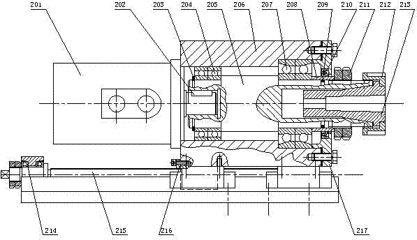
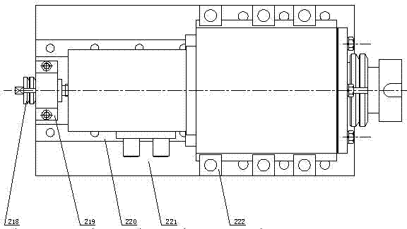
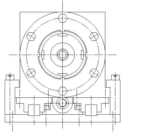
[0026] Such as Figure 5 , 6 As shown, the drilling and milling head 2 of the present invention is fixed on the front end surface of the movable disk 1 of the pipe cutting machine. The fixed seat 3 of the pipe cutting machine is installed on the pipe through the clamping legs 4, and forms a concentric circle structure with the pipe. Drilling and milling head power unit assembly 2 just can realize the circular rotation around pipe along with pipe cutting machine movable plate 1 and do cutting processing feeding motion. The drilling and milling head power assembly 2 clamps the milling cutter and drives the milling cutter to rotate to perform the main movement of cutting. The drilling and milling head power assembly 2 can also realize the manual rotation of the lead screw to realize the radial feed movement along the radial direction of the pipeline.

[0027] Such as figure 1 , figure 2 As shown, the drilling and milling head 2 is installed on the front end of the movable p...


PUM


Abstract

The invention discloses a drilling and milling head. The drilling and milling head is arranged on the front end face of a moving disk of a tube cutter through a bottom plate; two parallel linear guide rails are fixedly arranged on the bottom plate; a box is fixedly arranged on the linear guide rails; a screw is arranged on the bottom plate through a supporting seat, and forms a screw-nut pair with the box; the box can move along the linear guide rails under the drive of the screw; a hydraulic motor is fixedly arranged on the back end face of the box through a square flange; the motor shaft extends into a cylindrical hole at the back end of a main shaft, and is connected with the cylindrical hole through a key; the main shaft is in a single-pivot bidirectional fixation formation; a cutter is connected with a collet into a whole; a wedge cushion block is arranged on the moving disk of the tube cutter; a drilling and milling head power device assembly is fixedly arranged on the wedge cushion block, so that the angle of inclination of the drilling and milling head power device assembly is changed, the cutter is inclined in the milling process, a welding groove is directly formed on the end face of a pipeline in the process of cutting the pipeline, and tube cutting and groove formation are integrated. The drilling and milling head is simple in structure and easy to implement.

Description

technical field [0001] The invention relates to a rapid repair equipment for fluid pipelines, in particular to a drilling and milling head of a pipeline cutting machine for cutting pipelines. Background technique [0002] Once a Type A accident that requires large-scale maintenance and repair operations occurs in an oil and gas pipeline, first, the loss is huge, and second, maintenance and repair work is urgent, requiring the use of large-scale plugging equipment and repair tools. For pipe replacement, the pipe is generally cut at both ends of the damaged position, then the pipe ends are beveled, and finally the pipe is welded. Therefore, the pipe cutting machine is one of the important equipment in the pipeline maintenance and repair construction. At present, when cutting accident pipelines, wire saws, guillotine pipe saws, turning or milling with saw blades are usually used. However, these methods of cutting pipelines have the following problems: 1. Many pipelines need to...

Claims


Application Information

Patent Timeline
IPC IPC(8): B23Q5/06B23Q5/32B23B19/02B23Q3/12
CPCB23Q1/70B23Q5/06B23Q5/32B23Q2705/026B23Q2705/04B23Q2705/16
Inventor 葛汉林吴明董守海姜芳王平邓子龙
Owner LIAONING UNIVERSITY OF PETROLEUM AND CHEMICAL TECHNOLOGY
Learn More