Potted photovoltaic junction box

A volt junction box and glue filling technology, which is applied in the field of photovoltaic power generation, can solve the problems of wasting power resources, increasing the thickness and volume of photovoltaic junction boxes, and difficulty in achieving heat dissipation, so as to increase internal space, improve heat dissipation performance, and heat dissipation area big effect

Active Publication Date: 2014-04-02
浙江鑫辉光伏科技有限公司
View PDF7 Cites 2 Cited by
  • Summary
  • Abstract
  • Description
  • Claims
  • Application Information

AI Technical Summary

Problems solved by technology

Since the diode will generate a higher temperature during operation, as the temperature of the diode continues to rise, the resistance in the diode will continue to increase, causing the diode to generate more heat, thereby wasting more power resources and entering a vicious circle
In order to ensure better heat dissipation of the photovoltaic junction box, the method of increasing the volume of the installation cavity in the photovoltaic junction box is generally adopted, thereby increasing the thickness and volume of the entire photovoltaic junction box. More importantly, it is difficult to achieve good heat dissipation by using this method cooling effect

Method used


Image

  • Potted photovoltaic junction box
  • Potted photovoltaic junction box
  • Potted photovoltaic junction box

Examples


Embodiment Construction

[0022] The specific embodiments of the present invention will be further described below in conjunction with the accompanying drawings.

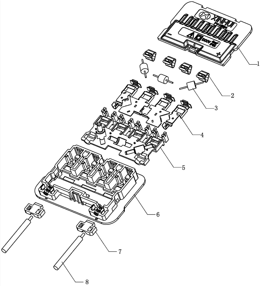
[0023] Such as figure 1 As shown, the present invention includes a base 6 and an upper cover 1 that cover each other. A bottom plate 5 is installed in the base 6 . A plurality of terminals 4 of different shapes, a plurality of belt clips 2 and a plurality of diodes 3 are installed on the bottom plate 5 . See Figure 6 , the installation method is to install diodes 3 between adjacent terminals 4, and to install belt clips 2 on each terminal 4 respectively. Such as figure 1 As shown, two crimping buckles 7 are installed in the base 6 , and two photovoltaic cables 8 respectively pass through the crimping buckles 7 and are welded to the terminals 4 .

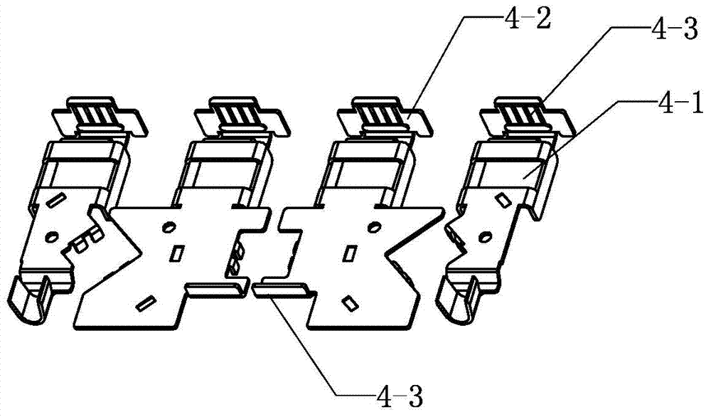
[0024] Such as image 3 As shown, each terminal 4 has a bus strip hole 4-1 for the bus strip to pass through, and a solder groove 4-3 for the bus strip to weld. When the bus strip (not shown ...


PUM


Abstract

The invention discloses a potted photovoltaic junction box. The potted photovoltaic junction box comprises a base and an upper cover, which are buckled mutually, wherein a bottom plate is mounted in the base; terminals are mounted on the bottom plate; band clamps and diodes are mounted on the terminals; photovoltaic cables penetrate through cable pressing buckles mounted in the base and is connected with the terminals; the interior of the base, in a position above the bottom plate, is filled with a sealant. According to the potted photovoltaic junction box, the hottest part is not in direct contact with a solar back panel, a convection cavity is formed in the bottom of the base, the bottom surface of the base forms a height difference with the bottom plate, and ventilation holes are formed in the upper cover, so that good radiation effects are achieved; the inner cavity of a box body is filled with metal parts, so that a large radiation area after potting is ensured, and heat is uniformly distributed; the periphery of the base is bent to form hoardings, and cavities are formed through the hoardings, so that the potting volume is reduced, and meanwhile, the radiation speed is increased; convex plates are additionally arranged at the edges of the terminals, so that the effect of enlarging the radiation area is achieved; a busbar is fixed in dual ways of welding and clamping, and the terminals, the bottom plate and the base are firmly connected, so that high reliability is ensured; lug bosses are used as fulcrums, so that the clamps can be conveniently pried to realize mounting and dismounting.

Description

technical field [0001] The invention relates to the field of photovoltaic power generation, in particular to a glue-filled photovoltaic junction box used in a photovoltaic power generation system. Background technique [0002] In the electrical connection technology of photovoltaic power generation systems, photovoltaic junction boxes are usually used to realize the electrical connection between photovoltaic modules and inverters. Since the application of the photovoltaic junction box is usually an outdoor environment, it is an important consideration in the design of the photovoltaic junction box to prevent the infiltration of rainwater and other media from affecting the internal electrical connection. The glue-filled photovoltaic junction box is sealed and waterproof by filling glue, which is a better solution at present. The current glue-filled photovoltaic junction box is the same as the ordinary junction box, and an installation cavity is provided between the box bodie...

Claims


Application Information

Patent Timeline
Patent Type & Authority Applications(China)
IPC IPC(8): H02S40/34
CPCY02E10/50
Inventor 彭祁军李艳群
Owner 浙江鑫辉光伏科技有限公司
Why Eureka
Try Eureka