
Cylindrical reinforcing steel bar connecting method and connecting structure in reverse building method

A connection method and a technology for connecting structures, which are applied in infrastructure engineering, excavation, construction, etc., can solve problems such as long construction period, heavy welding workload, and enhanced brittleness, so as to reduce welding workload, reduce welding workload, and prevent The effect of foundation pit uplift

Inactive Publication Date: 2014-04-09
NO 2 CONSTR GRP CO LTD OF SHANGHAI CONSTR GRP
View PDF6 Cites 3 Cited by
  • Summary
  • Abstract
  • Description
  • Claims
  • Application Information

AI Technical Summary

Problems solved by technology

During the specific operation, the top end of the connecting steel bar 3 is threadedly connected in the sleeve 1-2 of the reserved column inserting bar 1-1 in the upper horizontal support structure 1, but at this time, the bottom end of the connecting steel bar 3 cannot be connected with the lower horizontal support structure 2. The sleeve 2-2 of the reserved column inserting rib 2-1 is threaded, and can only be fixed by welding
However, fixing steel bars by welding will reduce their plasticity and increase their brittleness; moreover, there are usually about 70 to 80 steel bars in each vertical load-bearing member. , especially unfavorable is that in the reverse method, for the welding work at the joint of the sleeve 2-2 connecting the lower part of the steel bar 3 and the column inserting bar 2-1, the construction personnel need to lean over to operate, and the smoke and dust generated during the welding process and harmful The gas easily invades the respiratory tract and seriously endangers human health. It can be seen that the connection method and connection structure of the column inserts in the above-mentioned vertical load-bearing members need to be improved urgently

Method used


Image

  • Cylindrical reinforcing steel bar connecting method and connecting structure in reverse building method
  • Cylindrical reinforcing steel bar connecting method and connecting structure in reverse building method
  • Cylindrical reinforcing steel bar connecting method and connecting structure in reverse building method

Examples


Embodiment 1

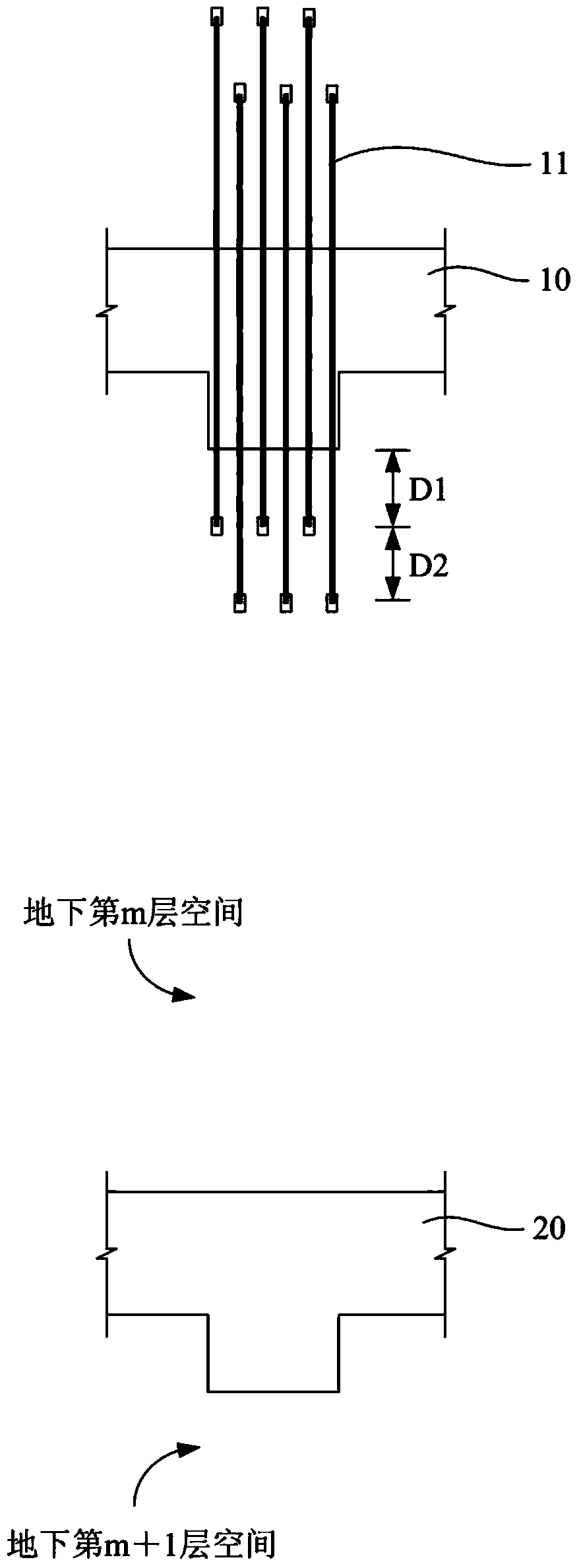
[0026] Example 1: Combining Figure 2 to Figure 4 Illustrate the connecting method of column steel bar in a kind of inversion method of the present invention, concrete steps are as follows:

[0027] Step 1: If figure 2 As shown, a number of column inserts 11 are reserved in the beam 10 of the mth floor space underground, so that the bottom end of the column insert 11 passes through the beam 10 and is located in the interior space of the mth floor underground;

[0028] Step 2: processing several connecting steel bars 50;

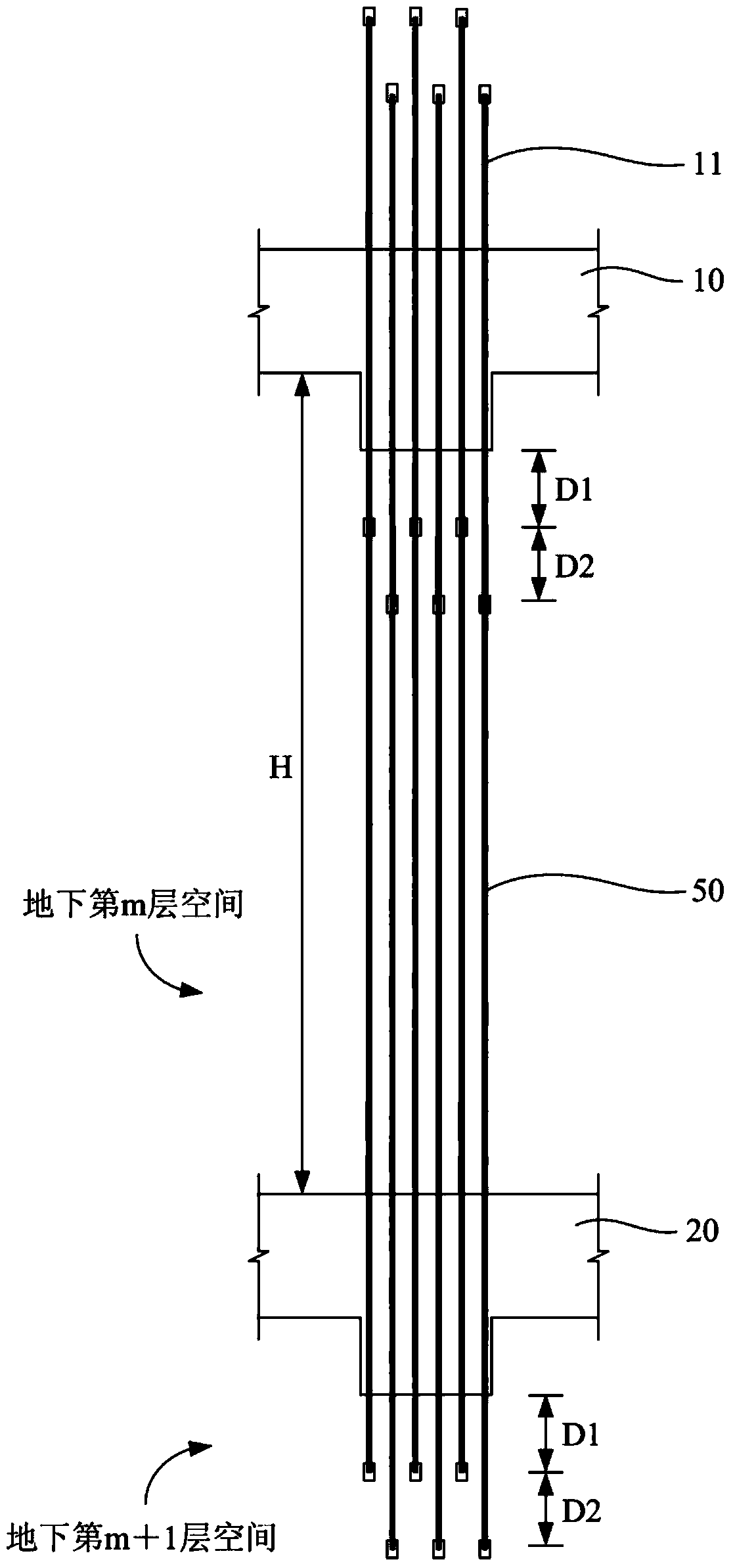
[0029] Step 3: If image 3 As shown, the top of the connecting steel bar 50 in the above step 2 is fixedly connected to the bottom end of the column insertion bar 11 reserved in the beam 10, and the bottom end of the above connecting steel bar 50 passes through the beam 20 in the space of the m+1th floor underground. The inner space of the m+1th underground floor forms the column reinforcement in the space of the mth underground floor;

[0030] Step 4: R...

Embodiment 2

[0036] Embodiment 2: Combination Figure 2 to Figure 4 The connection structure of the column reinforcement in a reverse method of the present invention includes a plurality of connection reinforcements 50, and the top of each connection reinforcement 50 is fixedly connected with the column insertion reinforcement 11 reserved in the beam 10 of the underground m-th floor space , the bottom end of each connecting rib 50 passes through the beam 20 in the space of the m+1th underground floor and enters the inner space of the m+1th underground floor.

[0037] Further, the top end of the connecting steel bar 50 is provided with an external thread, and its bottom end is connected to a sleeve with an internal thread. The top of the connecting steel bar 50 is threadedly connected to the sleeve at the bottom of the column inserting bar 11 in the beam 10, and the bottom end of the connecting bar 50 passes through the beam 20 to become the column inserting bar reserved in the beam 20 in t...


PUM


Abstract

The invention provides a cylindrical reinforcing steel bar connecting method and connecting structure in a reverse building method, and relates to the technical field of site manufacturing of building materials or building components. The problems that an existing cylindrical inserting bar is multiple in connecting welding spot, the plasticity of steel bars is lowered, the brittleness of the steel bars is enhanced, welding workloads are large, and the consumption of steel is large are solved. The cylindrical reinforcing steel bar connecting method comprises the steps that first, cylindrical inserting bars are reserved in a cross beam in the underground mth layer of space; second, connecting steel bars are machined; third, the top ends of the connecting steel bars are fixedly connected with the cylindrical inserting bars in the underground mth layer of space, and the bottom ends of the connecting steel bars penetrate through a cross beam in the underground (m+1)th layer of space to enter the inside space; fourth, the second step and the third step are repeatedly executed to form cylindrical steel bars in the underground (m+1) layer of space, in this way, circulation is conducted to form cylindrical steel bars in the underground (m+n)th layer of space, and the m and the n are integers larger than or equal to one. The connecting structure comprises a plurality of connecting steel bars, the top ends of the connecting steel bars are fixedly connected with the cylindrical inserting bars in the cross beam in the underground mth layer of space, the bottom ends of the connecting steel bars penetrate through the cross beam in the underground (m+1)th layer of space to enter the inside space in the underground (m+1)th layer.

Description

technical field [0001] The invention relates to the technical field of on-site preparation of building materials or building components, in particular to a connection method and connection structure of column steel bars in the reverse method. Background technique [0002] The upside-down construction technology is often used in deep foundation pit engineering in soft soil areas. In the excavation of deep foundation pits in soft soil areas, foundation pit support must be carried out. The foundation pit support system consists of an external maintenance structure and an internal support system. The maintenance structures outside the foundation pit are generally underground diaphragm walls (or reinforced concrete support piles) and cement mixing piles. Because the deformation of the maintenance structure outside the foundation pit increases with the deepening of the earth excavation, in order to reduce the deformation of the foundation pit, several horizontal supports are usua...

Claims


Application Information

Patent Timeline
IPC IPC(8): E02D17/04
Inventor 谢德强李凯阳
Owner NO 2 CONSTR GRP CO LTD OF SHANGHAI CONSTR GRP
Learn More