
Double-capillary-core evaporator applied to flat-type LHP system

A capillary core and evaporator technology, applied in the field of double capillary core evaporators, can solve problems such as fluctuations in operating temperature and pressure, increase in system operating temperature, and increase in internal pressure, so as to reduce operating temperature, reduce operating fluctuations, and reduce operating temperature. The effect of drag reduction

Active Publication Date: 2014-04-09
HUAZHONG UNIV OF SCI & TECH
View PDF5 Cites 26 Cited by
  • Summary
  • Abstract
  • Description
  • Claims
  • Application Information

AI Technical Summary

Problems solved by technology

The temperature rise of the compensation chamber leads to a phase change of the liquid in the compensation chamber. The compensation chamber is in a gas-liquid two-phase state, and the internal pressure increases, which increases the resistance of the system operation, thus increasing the operating temperature of the system.
When the compensation cavity is in the gas-liquid two-phase, the heat conduction of the side wall can cause the generation and annihilation of bubbles in the compensation cavity, which will adversely affect the operating temperature and pressure of the system.

Method used


Image

  • Double-capillary-core evaporator applied to flat-type LHP system
  • Double-capillary-core evaporator applied to flat-type LHP system
  • Double-capillary-core evaporator applied to flat-type LHP system

Examples


Embodiment Construction

[0037] In order to make the object, technical solution and advantages of the present invention clearer, the present invention will be further described in detail below in conjunction with the accompanying drawings and embodiments. It should be understood that the specific embodiments described here are only used to explain the present invention, not to limit the present invention.

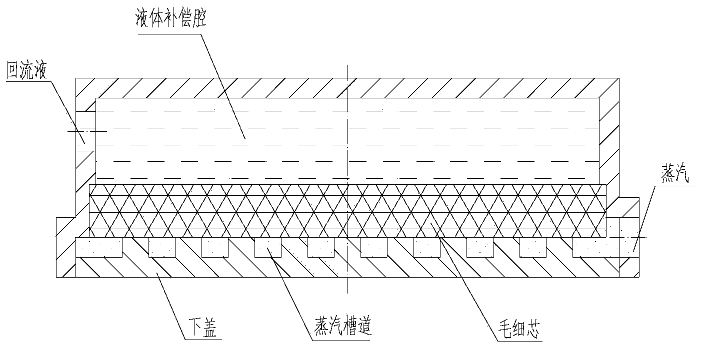
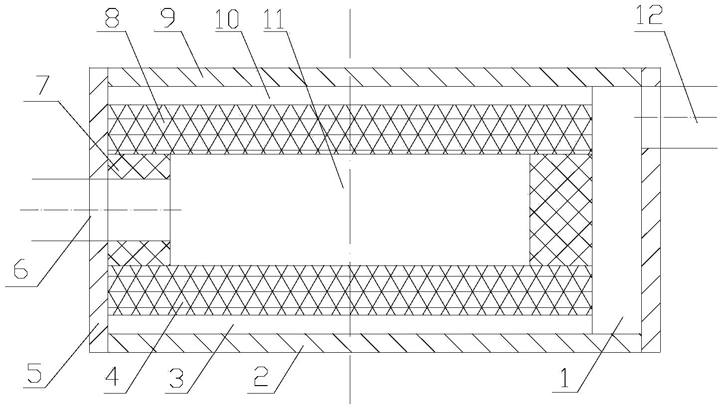
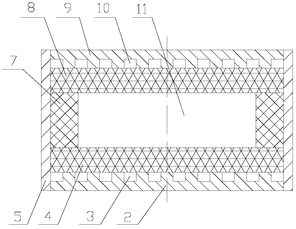
[0038] Such as Figure 2-3 As shown, the evaporator of the embodiment of the present invention is mainly composed of three parts: a main body 5 ; a lower end cover 2 and an upper end cover 9 ; a lower capillary core 4 , an upper capillary core 8 and a wire mesh 7 . Wherein the upper and lower end covers 2, 9 are fixedly connected with the main body 5 by welding. The steam cavity 1 is formed by the empty space after the circular capillary core is arranged on the preferably semi-elliptical body 5, and is used to collect the steam generated by each steam channel. The compensation chamber 11 is compo...


PUM


Abstract

The invention discloses a double-capillary-core evaporator applied to a flat-type LHP system. The double-capillary-core evaporator comprises a main body, a lower end cover, an upper end cover, a lower capillary core, an upper capillary core and a wire mesh. The upper end cover and the lower end cover are fixedly arranged on the two end faces of the main body respectively, and a plurality of through grooves are respectively formed in the upper end cover and the lower end cover to form an upper steam channel and a lower steam channel. The upper capillary core and the lower capillary core are contained in closed space and are in close contact with the end covers respectively; the capillary cores are sealed through the wire mesh to define a compensation cavity, a steam cavity is formed by surplus space, located on one side of the compensation cavity, in the closed space, the steam cavity is communicated with a condensing device through a steam outlet, the compensation cavity is communicated with the outside through a backflow liquid pipe, and after steam flowing out from the steam channels is gathered to the steam cavity, the steam is condensed in the outside and flows into the compensation cavity from the backflow liquid pipe to compensate for working media in the upper capillary core and the lower capillary core. According to the double-capillary-core evaporator, the heat transmission capacity of the LHP system can be improved, influences of lateral wall heat conduction on the compensation cavity are reduced, the operation temperature of the LHP system is lowered, and the operation performance of the LHP system is improved.

Description

technical field [0001] The invention belongs to the technical field of capillary wick evaporators, in particular to a double capillary wick evaporator applied to a flat-plate LHP (Loop Heat Pipe: loop heat pipe) system, suitable for portable or desktop computers and other high heat flux electronic devices, etc. Heat dissipation of the device. Background technique [0002] LHP is a device that uses phase change of working fluid for heat transfer. It has the advantages of large heat transfer capacity, long transmission distance, no moving parts, high efficiency, good isothermal performance, etc., and is suitable for heat dissipation of high heat flux electronic devices. A traditional LHP system consists of evaporators, condensers, steam piping and liquid piping. The working process of LHP is: the heating surface of the evaporator is attached to the heating surface of the device, the heat is introduced into the capillary core through the wall surface of the evaporator, the li...

Claims


Application Information

Patent Timeline
IPC IPC(8): F28D15/04
Inventor 汪冬冬刘志春刘伟杨金国
Owner HUAZHONG UNIV OF SCI & TECH
Learn More