High-wall compact high-speed precision vertical machining center

A vertical machining center, compact technology, applied in the direction of metal processing, metal processing equipment, metal processing machinery parts, etc., can solve the problems of low precision, poor overall rigidity, old structure, etc., achieve high metal removal rate and improve rigidity State, the effect of improving rigidity

Inactive Publication Date: 2014-04-16
JINAN FIRST MACHINE TOOL GROUP
View PDF7 Cites 2 Cited by
  • Summary
  • Abstract
  • Description
  • Claims
  • Application Information

AI Technical Summary

Problems solved by technology

[0002] The main problem of the current vertical machining center is that the structure is old, and all of them are the most primitive so-called "C" layout. The disadvantage of this structure is that the overhang of each axis of the machine tool is large, the overall rigidity is poor, and the accuracy and fast moving speed cannot be effectively obtained. Improvement; using this machine tool for mold processing can only meet the needs of general medium and low precision; on the basis of this series of models, it is almost impossible to realize the upgrade and modification of the five-axis linkage of the machine tool
Therefore, such low-tech products have low technical threshold, high penetration rate, similar product technology, fierce market competition, and it is difficult to talk about profitability and economic benefits.

Method used


Image

  • High-wall compact high-speed precision vertical machining center
  • High-wall compact high-speed precision vertical machining center
  • High-wall compact high-speed precision vertical machining center

Examples


Embodiment Construction

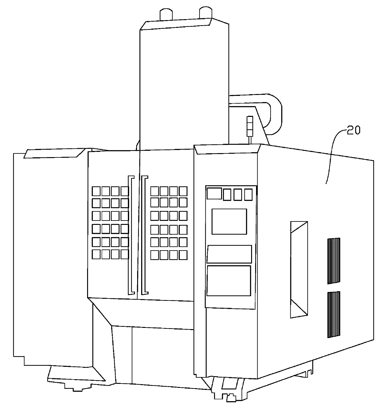
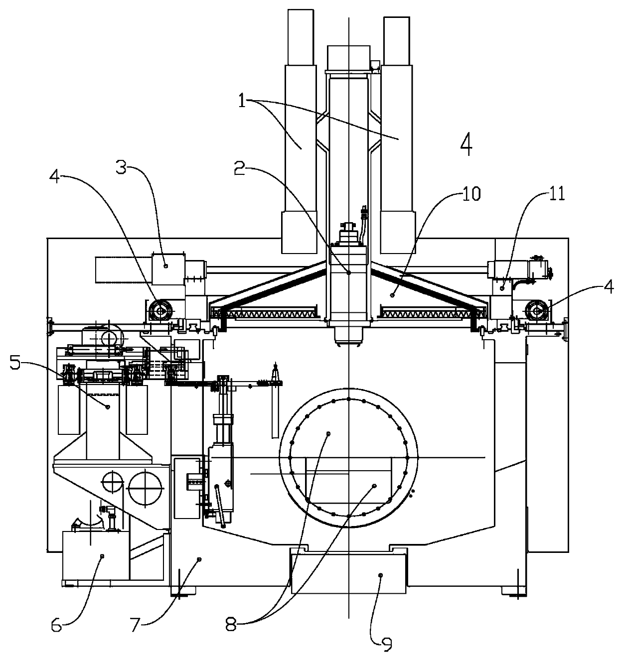
[0027] like figure 1 , 2 , 3, the high-wall compact high-speed precision vertical machining center includes a spindle box 2, an oil tank 6, a tool magazine 5, a bed base 7, an X-direction feed mechanism 3, a Y-direction feed mechanism 4, and a Z-direction feed mechanism. Giving mechanism 1; Also comprise protective cover 20; Described main shaft box 2 comprises main shaft housing and main shaft; Its special feature is:

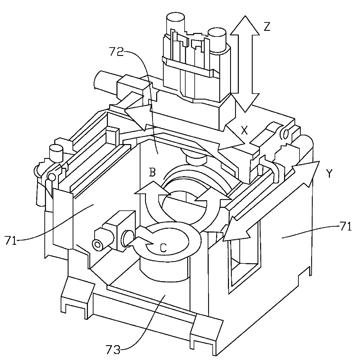
[0028] The bed base 7 includes a box-type structure formed by sealing and connecting three vertical walls and a chassis 73; the three vertical walls are respectively two side vertical walls 71 and a rear vertical wall 72; the X-direction feed mechanism 3 is arranged on the The top of the rear vertical wall 72; the Y feed mechanism 4 is arranged on the top of the side vertical wall 71, and the Z feed mechanism 1 is also arranged on the top of the rear vertical wall 72;

[0029] The machining center also includes a B, C-axis double-swing axis workbench 8 equip...


PUM


Abstract

Provided is a high-wall compact high-speed precision vertical machining center. The high-wall compact high-speed precision vertical machining center is characterized in that a lathe base is of a box type structure which is composed of three vertical walls and a base plate in a sealing connection mode, an X-direction feeding mechanism is arranged on the top of the rear vertical wall, a Y-direction feeding mechanism is arranged on the top of one side vertical wall, and a Z-direction feeding mechanism is also arranged on the top of the rear vertical wall; the high-wall compact high-speed precision vertical machining center further comprises a B-axis and C-axis double-pendulum workbench which is arranged in the space defined by the lathe base, and is provided with a circular grating; center blind holes are formed in a lead screw of the X-direction feeding mechanism, a lead screw of the Y-direction feeding mechanism and a lead screw of the Z-direction feeding mechanism respectively, steel tubes are arranged in the center blind holes respectively, inner cavities of the steel tubes serve as liquid inlet flow channels, and are communicated with cooling liquid inlets respectively, a liquid turning flow channel is formed by one end of each steel tube and the blind end of the corresponding blind hole, and a liquid outlet flow channel is formed between the outer wall of each steel tube and the inner wall of the corresponding blind hole, and is communicated with a cooling liquid outlet. According to the high-wall compact high-speed precision vertical machining center, the purposes that the lengths of overhanging portions of shafts of a lathe are small, the overall rigidity is good, accuracy is improved, and the speed of rapid movement is increased can be achieved.

Description

technical field [0001] The invention relates to a machining center for machining metal workpieces, in particular to a high-wall compact high-speed precision vertical machining center. Background technique [0002] The main problem of the current vertical machining center is that the structure is old, and all of them are the most primitive so-called "C" layout. The disadvantage of this structure is that the overhang of each axis of the machine tool is large, the overall rigidity is poor, and the accuracy and fast moving speed cannot be effectively obtained. Improvement; the use of this machine tool for mold processing can only meet the needs of general medium and low precision; on the basis of this series of models, it is almost impossible to realize the upgrade and modification of the five-axis linkage of the machine tool. Therefore, such low-tech products have low technical threshold, high penetration rate, similar product technology, fierce market competition, and it is di...

Claims


Application Information

Patent Timeline
Patent Type & Authority Applications(China)
IPC IPC(8): B23Q37/00B23Q11/08B23Q5/40B23Q1/64
CPCB23Q37/00B23Q1/015B23Q5/40B23Q11/126
Inventor 刘志龙张本立孙章魁彭蕤张志强
Owner JINAN FIRST MACHINE TOOL GROUP
Why Eureka
Try Eureka