Reciprocating push plate wind turbine

A wind turbine and push plate technology, which is applied to wind turbines, wind energy power generation, engines and other directions, can solve the problems of low wind energy utilization coefficient, inconvenient movement, fixed and no longer movable, etc., and achieves high wind energy utilization rate and wind energy utilization. High coefficient, easy to use and move

Active Publication Date: 2016-04-06
陈阿红
View PDF5 Cites 0 Cited by
  • Summary
  • Abstract
  • Description
  • Claims
  • Application Information

AI Technical Summary

Problems solved by technology

[0002] At present, wind power generators have been widely used in the field of power generation. Existing wind power generators generally generate electricity by driving the blades to rotate by wind force. This power generation method mainly has the following disadvantages: 1. It is troublesome to install, and it is generally fixed after installation. No longer moving, it is very inconvenient to move; 2. When the blades generate electricity, a large part of the wind will leak from the gap between the blades, the wind energy utilization coefficient is low, and the utilization rate of wind energy is greatly reduced; 3. The wind blows the paddle When the blade rotates for a long time, the blade is easy to break, and there is a certain safety hazard; 4. The noise generated when the blade rotates is relatively large, resulting in a certain amount of noise pollution

Method used


Image

  • Reciprocating push plate wind turbine
  • Reciprocating push plate wind turbine
  • Reciprocating push plate wind turbine

Examples


Embodiment Construction

[0019] In order to clearly illustrate the technical characteristics of this solution, the following describes the present invention in detail through specific implementations and in conjunction with the accompanying drawings.

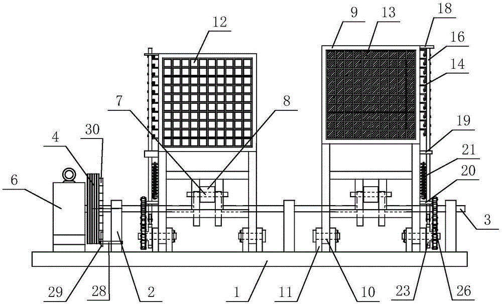
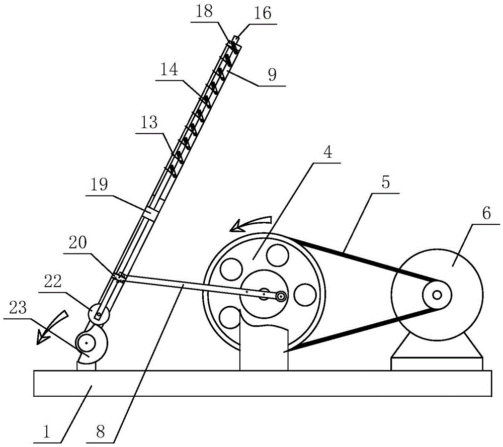
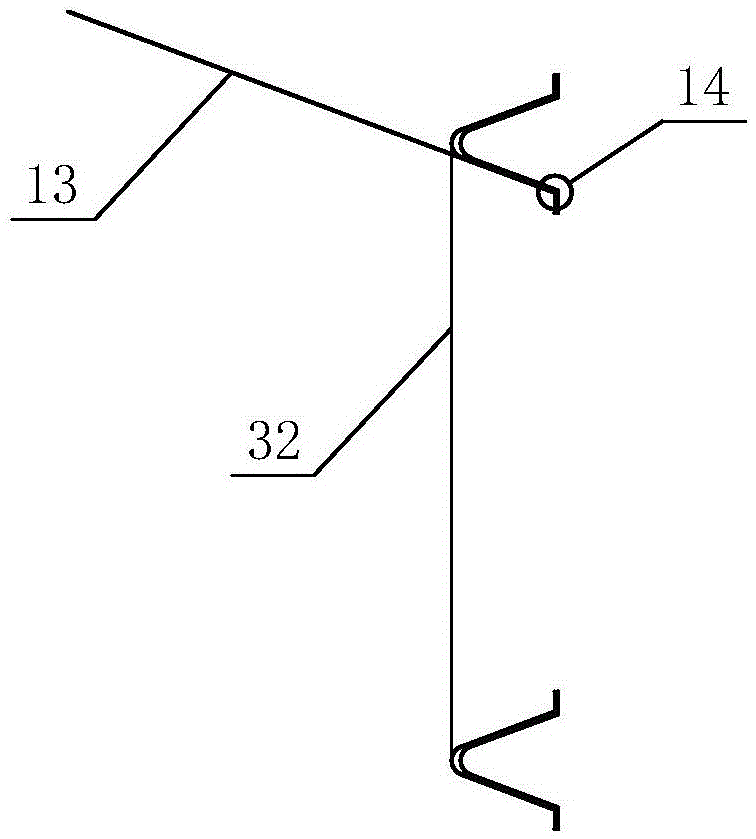
[0020] Such as Figure 1-8 As shown, a reciprocating push-plate wind power generator includes a base 1, a crankshaft 3 is movably installed on the base 1 through a number of crankshaft pads 2, and one end of the crankshaft 3 is fixedly connected to a large crankshaft pulley 4, The seat 1 is provided with a one-way rotating device that is matched with the large crankshaft pulley 4, and the large crankshaft pulley 4 is connected to the pulley on the input shaft of the generator 6 provided on the base 1 through the V-belt 5; At least two crank arms 7 with the same turning diameter are arranged at the upper interval, and each crank arm 7 is arranged in a staggered and uniform manner along the circumference of the crankshaft 3. On the base 1 on one side of the c...


PUM


Abstract

The invention relates to a reciprocating push plate type wind driven generator, which comprises an engine base, wherein a crankshaft is movably arranged on the engine base through a plurality of crankshaft bearing seats, one end of the crankshaft is fixedly connected with a large crankshaft belt wheel, the engine base is provided with a unidirectional rotating device which is matched with the large crankshaft belt wheel, the large crankshaft belt wheel is connected with a belt wheel on an input shaft of a generator, arranged on the engine base, through a triangular belt; at least two crank arms with equal crank diameter are arranged on the crankshaft at intervals and are evenly arranged oppositely along with the periphery of the crankshaft, the engine base on one side of the crankshaft is provided with a wind plate assembly corresponding to the position of each crank arm, each crank arm is hinged with one end of a connecting rod respectively, the wind plate assembly opposite to the crank arm in position is hinged with the other end of the connecting rod, and the lengths of all connecting rods are equal. The reciprocating push plate type wind driven generator is reasonable in structure design, can be used without construction and installation, can be wholly transported, and is convenient to use and move; the reciprocating push plate type wind driven generator is safe and reliable to work, and small in noise, high in wind energy utilization coefficient and wind energy utilization rate, and suitable for being widely popularized and used.

Description

Technical field: [0001] The invention relates to a reciprocating push plate type wind power generator. Background technique: [0002] At present, wind turbines have been widely used in the field of power generation. The existing wind turbines generally generate electricity through the rotation of the blades driven by the wind. This type of power generation mainly has the following disadvantages: 1. Installation is troublesome, and it is generally fixed after installation No longer moving, it is very inconvenient to move; 2. When the blades are generating electricity, a large part of the wind will leak from the gap between the blades, the wind energy utilization coefficient is low, and the utilization rate of wind energy is greatly reduced; 3. When the blade rotates for a long time, the blade is easy to break, and there is a certain safety hazard; 4. The noise generated when the blade rotates is relatively large, which causes a certain amount of noise pollution. Summary of the in...

Claims


Application Information

Patent Timeline
Patent Type & Authority Patents(China)
IPC IPC(8): F03D5/00
CPCY02E10/70
Inventor 陈阿红李波付乃旭付乃波陈亦栋
Owner 陈阿红
Why Eureka
Try Eureka