
A method of manufacturing shallow trench isolation

A manufacturing method and technology of shallow trenches, which are applied in semiconductor/solid-state device manufacturing, electrical components, circuits, etc., can solve problems such as poor isolation quality of shallow trenches, improve performance and yield, reduce wet etching rate, and improve performance effect

Active Publication Date: 2016-11-30
SEMICON MFG INT (SHANGHAI) CORP
View PDF5 Cites 0 Cited by
  • Summary
  • Abstract
  • Description
  • Claims
  • Application Information

AI Technical Summary

Problems solved by technology

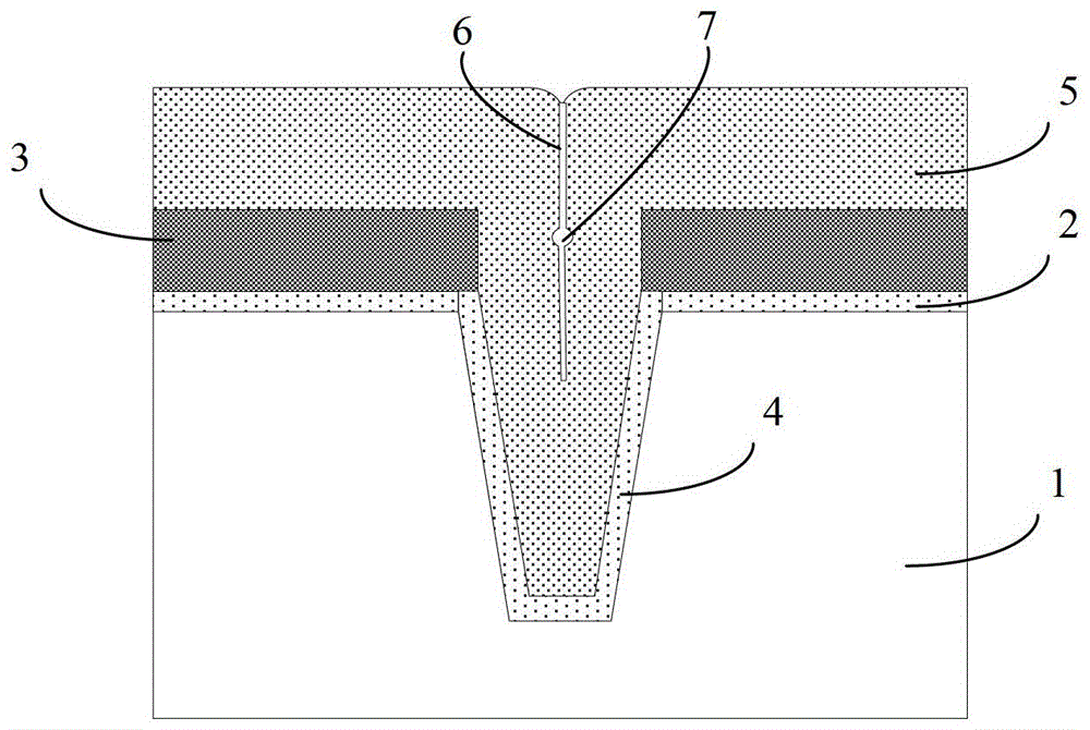
[0006] The purpose of the present invention is to provide a manufacturing method of shallow trench isolation to solve the problem of poor quality of shallow trench isolation formed in the prior art

Method used


Image

  • A method of manufacturing shallow trench isolation
  • A method of manufacturing shallow trench isolation
  • A method of manufacturing shallow trench isolation

Examples


Embodiment Construction

[0032] The manufacturing method of the shallow trench isolation provided by the present invention will be further described in detail below with reference to the accompanying drawings and specific embodiments. Advantages and features of the present invention will be apparent from the following description and claims. It should be noted that all the drawings are in a very simplified form, and are only used for the purpose of conveniently and clearly assisting in describing the embodiments of the present invention.

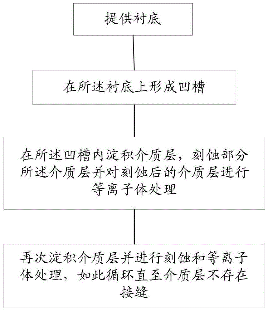
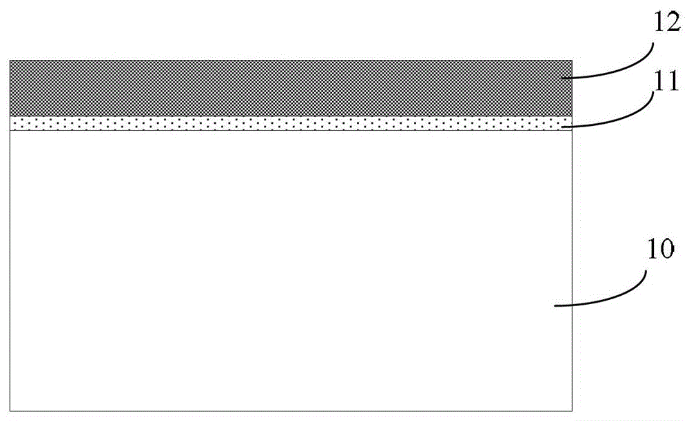
[0033] Please refer to figure 2 The flowchart provided and Figure 3 to Figure 9 The schematic cross-section of the device is shown.

[0034] Such as image 3 As shown, a substrate 10 is provided. The substrate 10 can be, for example, a silicon substrate. A layer of pad oxide layer 11 is formed on the surface of the substrate 10, and a layer of silicon nitride layer is formed on the pad oxide layer 11. 12. The pad oxide layer 11 and the silicon nitride layer 12...


PUM


Abstract

The invention discloses a manufacturing method of shallow trench isolation, which adopts the cycle of firstly depositing a dielectric layer in the shallow trench, etching part of the dielectric layer, and then performing plasma treatment on the etched dielectric layer. The process can make the deposited dielectric layer denser, and at the same time reduce the wet etching rate of the dielectric layer, thereby avoiding the formation of seams and / or pores, and also avoiding the erosion of the dielectric layer by wet cleaning, which greatly improves the The performance of the STI is improved, which is conducive to improving the performance and yield of the device.

Description

technical field [0001] The invention relates to the field of integrated circuit manufacturing, in particular to a method for manufacturing shallow trench isolation. Background technique [0002] In the advanced complementary metal-oxide-semiconductor (CMOS) industry, the feature size of devices is continuously shrinking, and the components that make up the circuit are denser, so the effective isolation between circuits becomes more important. That is, the shallow trench isolation (STI) in the prior art must have better insulation properties. [0003] In order to deal with STI in complex areas, a variety of filling methods have been developed, such as chemical vapor deposition (CVD) and plasma enhanced chemical vapor deposition (PECVD). In addition, sputtering processes can also be used, followed by chemical mechanical polishing ( CMP) process to planarize the surface. [0004] At present, for the CMOS manufacturing process of 45nm and below nodes, sub-atmospheric chemical ...

Claims


Application Information

Patent Timeline
Patent Type & Authority Patents(China)
IPC IPC(8): H01L21/762
Inventor 周鸣
Owner SEMICON MFG INT (SHANGHAI) CORP
Learn More