Liquid crystal display

A technology of liquid crystal display device and liquid crystal layer, which is applied in the directions of instruments, optics, nonlinear optics, etc., can solve the problems of low transmittance of white display and the like

Active Publication Date: 2014-04-16
SHARP KK
View PDF16 Cites 10 Cited by
  • Summary
  • Abstract
  • Description
  • Claims
  • Application Information

AI Technical Summary

Problems solved by technology

However, in the conventional MVA-LCD, the upper part of the protrusion or the upper part of the slit becomes the boundary of the alignment division of

Method used


Image

  • Liquid crystal display
  • Liquid crystal display
  • Liquid crystal display

Examples


Embodiment approach 1

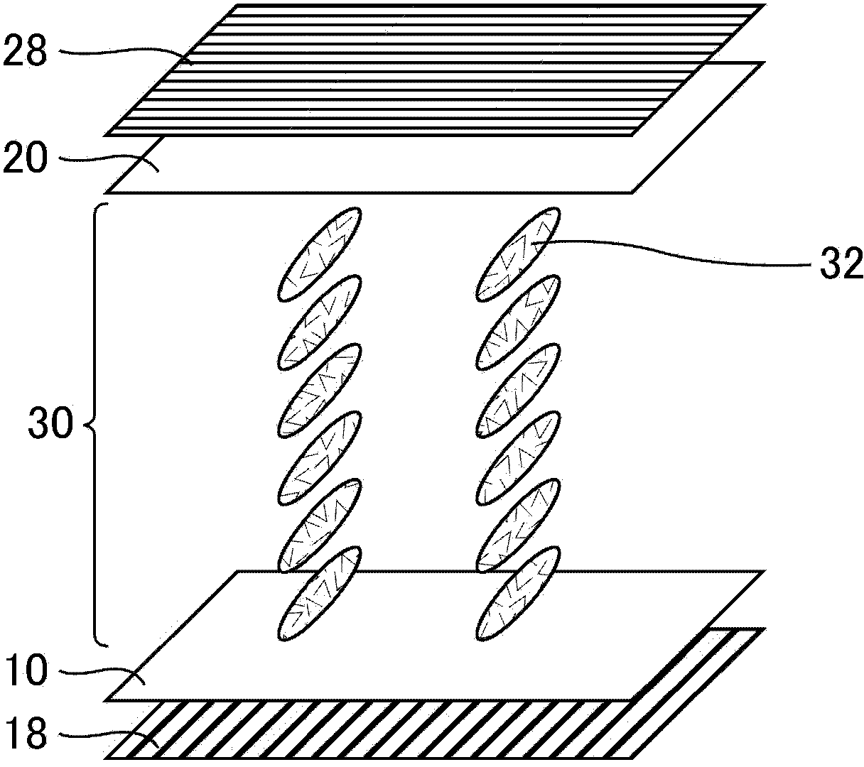
[0108] Embodiment 1 is a liquid crystal display device in which the direction of the polarization transmission axis of the polarizing plate on the front side (observation side) is perpendicular to the liquid crystal alignment direction (initial alignment). The display mode adopts IPS mode. figure 1 It is a schematic perspective view of the liquid crystal display device according to Embodiment 1 when the voltage is lower than the threshold voltage. In the liquid crystal display device according to Embodiment 1, the array substrate 10 , the liquid crystal layer 30 and the color filter substrate 20 are stacked sequentially from the back side of the liquid crystal display device toward the viewing side to form a liquid crystal cell. A rear-side polarizing plate 18 and a front-side polarizing plate 28 are respectively provided on the rear side of the array substrate 10 and the viewing surface side of the color filter substrate 20 .

[0109] exist figure 1 In , the direction of ...

Embodiment 1)

[0122] Prepare a glass substrate (comb-teeth electrode substrate) and a bare glass substrate (counter substrate) having a pair of comb-teeth electrodes as transparent electrodes on the surface, and apply polymer as a material for a horizontal alignment film on each substrate by spin coating. Vinyl cinnamate solution. As the glass of the glass substrate, #1737 (manufactured by Corning Incorporated) was used.

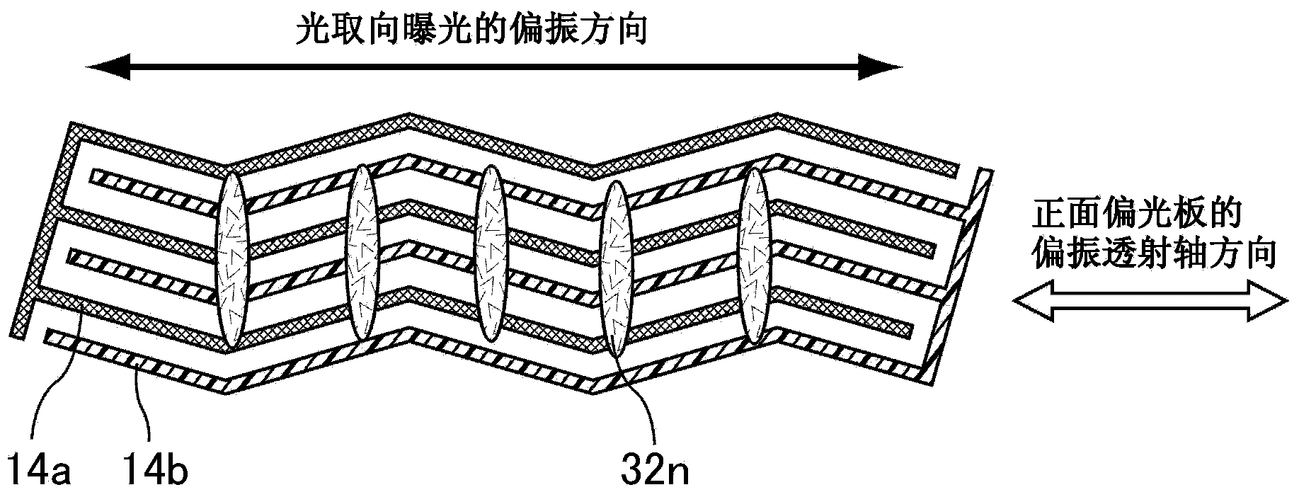
[0123] image 3 It is a schematic plan view showing the irradiation polarization direction, the comb-shaped electrodes, and the liquid crystal alignment direction of the liquid crystal display device according to the first embodiment. A pair of comb electrodes, such as image 3 As shown, the pixel electrode 14a and the common electrode 14b extend approximately parallel to each other, and are each formed in a zigzag shape. As a result, the electric field vector when the electric field is applied is substantially perpendicular to the longitudinal direction of the electro...

Embodiment approach 2

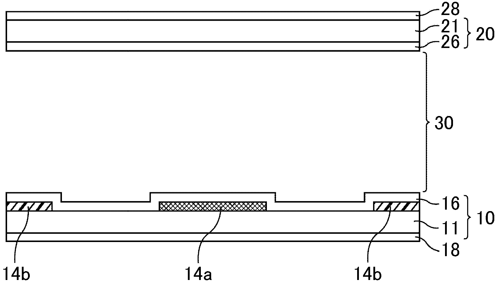
[0149] Embodiment 2 is the same as Embodiment 1, except that a PS layer is provided on the photo-alignment film, and liquid crystals are limited to preferred modes described later. Figure 8 is a schematic cross-sectional view of a liquid crystal display device according to Embodiment 2. FIG. The PS layers 117 and 127 can be polymerized by injecting a liquid crystal composition containing a liquid crystal material and a polymerizable monomer between the array substrate 110 and the color filter substrate 120, and irradiating a certain amount of light or heating the liquid crystal layer 130. Formed by polymerizing monomers. The PS layers 117 and 127 improve the orientation regulation force of the photo-alignment films 116 and 126 . In addition, at this time, by performing polymerization in a state where no voltage is applied to the liquid crystal layer 130 or a voltage lower than a threshold value is applied to the liquid crystal layer 130, the PS layers 117 and 127 having a sh...


PUM


Abstract

The present invention provides a liquid crystal display having light resistance, having stabilized liquid crystal alignment and having excellent display quality. In this liquid crystal display, at least one of a pair of substrates has a photo-alignment film and an electrode in that order from the liquid crystal layer. The photo-alignment film aligns liquid crystal molecules horizontally relative to said photo-alignment film, and the polarization transmission axis of a polarizing element on the observation surface side of a liquid crystal cell intersects the alignment direction of the liquid crystal molecules that are at less than a threshold voltage in the liquid crystal layer. The material configuring the photo-alignment film contains a material which, by means of polarized light irradiated onto the photo-alignment film, aligns the liquid crystal molecules in a direction intersecting the polarization direction of said polarized light.

Description

technical field [0001] The present invention relates to a liquid crystal display device. More specifically, it relates to a liquid crystal display device in which a polymer layer for improving properties is formed on an alignment film. Background technique [0002] A liquid crystal display (LCD: Liquid Crystal Display) is a display device that controls the transmission / blocking of light (display on / off) by controlling the orientation of birefringent liquid crystal molecules. Examples of LCD display methods include vertical alignment (VA: Vertical Alignment) mode in which liquid crystal molecules with negative dielectric constant anisotropy are vertically aligned with respect to the substrate surface, and liquid crystal molecules with positive or negative dielectric constant anisotropy. The in-plane switching (IPS: In-Plane Switching) mode in which the liquid crystal molecules are aligned horizontally with respect to the substrate surface and a transverse electric field is a...

Claims


Application Information

Patent Timeline
IPC IPC(8): G02F1/1337G02F1/1335
CPCG02F1/133788G02F1/1337C09K2323/00C09K2323/02G02F1/133711G02F1/133528G02F1/133738
Inventor 宫地弘一三宅敢
Owner SHARP KK
Why Eureka
Try Eureka