
Thermocoagulation surgical hemostat

A hemostat and surgery technology, applied in the direction of heating surgical instruments, etc., can solve the problems of affecting the normal operation of other instruments, polluting the environment, increasing costs, etc., and achieve the effects of flexible and convenient handle assembly, no pollution to the environment, and easy cleaning and disinfection

Inactive Publication Date: 2014-04-23
XINXIANG MEDICAL UNIV
View PDF7 Cites 7 Cited by
  • Summary
  • Abstract
  • Description
  • Claims
  • Application Information

AI Technical Summary

Problems solved by technology

High frequency will produce high-frequency radiation, pollute the environment, affect the normal work of other instruments, and also increase the cost

Method used


Image

  • Thermocoagulation surgical hemostat
  • Thermocoagulation surgical hemostat
  • Thermocoagulation surgical hemostat

Examples


Embodiment 1

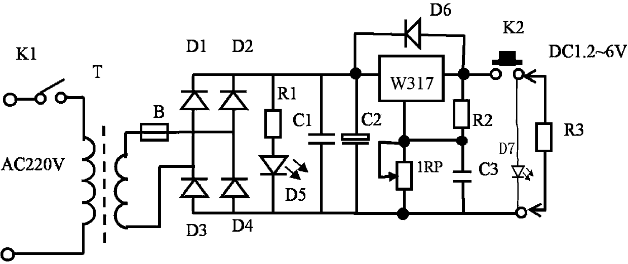
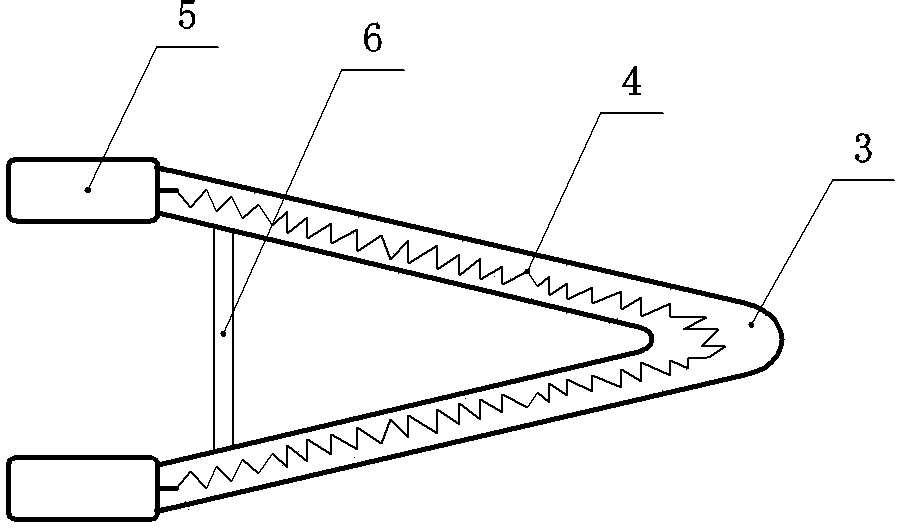
[0025] Such as figure 1 , image 3 , Figure 4 As shown, the present invention proposes a thermocoagulation surgical hemostat, including a heating control circuit, a hand-held thermal pen, the handheld thermal pen includes a handle 1 and a heating body 2, and the heating body 1 is composed of a hollow quartz glass tube 3 Composed of the heating wire 4 arranged therein, the shape of the hollow quartz glass tube is "V" or "U", and the connecting head 5 connected with the heating wire is drawn out from both ends of the hollow quartz glass tube. The front end of the handle 1 is provided with a connecting piece 9 matching the connecting head 5, and the heating wire is connected with the heating control circuit.

[0026] The thermal coagulation operation hemostat of the present invention, the front end working surface of the hollow quartz glass tube is a smooth arc, spherical, inclined or flat surface, and the heating body 2 is matched and connected with the connecting piece 9 at ...

Embodiment 2

[0028] see image 3 The difference between the thermal coagulation surgical hemostat of this embodiment and that of Embodiment 1 is that in order to increase the mechanical strength of the heating body, a reinforcing beam 6 is provided to connect the two branch sections of the "V" or "U" shaped hollow quartz glass tube. .

Embodiment 3

[0030] see Figure 4 The thermal coagulation surgical hemostat of this embodiment is different from Embodiment 1 or Embodiment 2 in that a temperature adjustment or / and heating control switch 7 is set on the handle 1, and the temperature adjustment or / and heating control switch is connected to the The heating control circuit described above.

[0031] A heating wire power-on indicator light 10 may be arranged on the handle for displaying the power-on state of the heating wire. The heating wire indicator light 10 is connected in parallel or in series with the heating wire.


PUM

PropertyMeasurementUnit
Lengthaaaaaaaaaa
Widthaaaaaaaaaa
Diameteraaaaaaaaaa

Abstract

The invention relates to a hemostatic device for surgical processes, in particular to a non-electric-contact thermocoagulation surgical hemostat comprising a heating control circuit and a handheld heating stylus composed of a handle and a heater. The heater comprises a hollow quartz glass tube and an electric heating wire disposed inside the same. The hollow quartz glass tube is V or U shaped. Connecting heads connected with the electric heating wire are led out of the two open ends of the hollow quartz glass tube. The front end of the handle is provided with a connector matching with the connecting heads. The electric heating wire is connected with a heating control circuit. The thermocoagulation surgical hemostat is simple in structure, low in manufacturing cost and convenient to use. The thermocoagulation surgical hemostat has the advantages that biological tissues or vessels can be coagulated instantly, tissue or vessel hemorrhage is reduced, surgical time is shortened, the thermocoagulation surgical hemostat is applicable to human surgeries and animal tests, harm of living things is reduced, the side effect is low, the use of low-voltage direct current electric heating causes no radiation, other instruments are not interfered, environmental pollution is avoided, and the thermocoagulation surgical hemostat is convenient to popularize and apply.

Description

technical field [0001] The invention relates to a hemostatic device during operation, in particular to a non-electrical contact thermal coagulation operation hemostat. Background technique [0002] During the operation, the commonly used hemostasis methods include instrumentation and electrocoagulation. Electrocoagulation methods include unipolar coagulation and bipolar coagulation. Monopolar coagulation is the first time that Cushing used the monopolar high-frequency coagulator designed by Bovie in neurosurgery in 1926. Its working principle is to use the high-frequency current of the monopolar electric knife to pass through the electric knife head, human tissue and patient plate It constitutes a complete circuit, and the tissue cells are rapidly dehydrated and coagulated during electrocoagulation, so as to achieve the purpose of hemostasis. In 1950, Mail designed bipolar coagulation. Its working principle is to apply high-frequency high-power sine waves, which are releas...

Claims


Application Information

Patent Timeline
IPC IPC(8): A61B18/12
Inventor 赵峰粱云真赵合运
Owner XINXIANG MEDICAL UNIV
Learn More