An optical luminescence dosimeter
A dosimetry and optical luminescence technology, applied in the direction of fluorescence/phosphorescence, material excitation analysis, etc., can solve the problems of not paying attention to the influence of adjacent samples, the influence of adjacent sample measurements, and the gap between optical fibers that cannot pass light, so as to simplify the sample lifting equipment , reduce the influence, increase the effect of optical coupling efficiency
- Summary
- Abstract
- Description
- Claims
- Application Information
AI Technical Summary
Problems solved by technology
Method used
Image
Examples
Embodiment 1
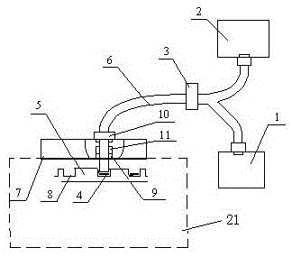
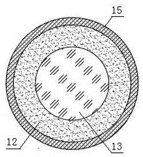
[0028] Optical Luminescent Dosimeter of the present invention such as figure 1 As shown, it includes an excitation light source 1, a photomultiplier tube 2, a beam splitter 3, a plastic optical fiber 6, a measuring instrument cover 7, a sample tray 5, a measuring instrument body 21, and an optical fiber moving mechanism. The optical fiber moving mechanism is fixed on the measuring instrument upper cover. superior. The optical fiber moving mechanism is connected with one end of the plastic optical fiber, and the other end of the plastic optical fiber is divided into two paths through a beam splitter, one path is connected to the excitation light source, and the other path is connected to the photomultiplier tube. Such as image 3 As shown, the plastic optical fiber 6 is composed of a single optical fiber core 13, an optical fiber coating layer 12 and an optical fiber outer layer 15, and the diameter of the optical fiber core is 10 mm. Depend on Figure 12 It can be seen that...
Embodiment 2
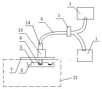
[0032] Another embodiment of the present invention, as shown in 2, includes an excitation light source 1, a photomultiplier tube 2, a beam splitter 3, a plastic optical fiber 6 and a measuring instrument body 21, and the measuring instrument body is provided with a measuring instrument upper cover 7 and a sample tray 5 And the worm gear moving mechanism, the worm gear moving mechanism includes a transmission device 14 and a motor module 16. One end of the plastic optical fiber is connected to the worm gear moving mechanism, and the other end is divided into two paths by a beam splitter, one path is connected to the excitation light source, and the other path is connected to the photomultiplier tube.
[0033] Such as Figure 5-7As shown, the transmission device is composed of a worm wheel 22, a worm screw 23 and a rack frame 25, and the motor module is provided with a stepping motor 24. The motor module is fixed on the measuring instrument upper cover 7, and the rack frame 25 ...
Embodiment 3
[0037] Yet another embodiment of the present invention is as Figure 8 As shown, the analyzer is provided with a sleeve 27 and a focusing lens 26 . The optical fiber moving mechanism is a magnetic flux moving mechanism, including a magnetic flux material 9, an optical fiber chuck 10, a positioning block 11 and a spring 17. The magnetic flux material, the optical fiber chuck, and the positioning block are provided with openings having the same outer diameter as the plastic optical fiber. The optical fiber chuck is fixed on the top of the measuring instrument upper cover 7 by bolts 19, and the magnetic flux material is fixed on the lower part of the measuring instrument upper cover by bolts. The plastic optical fiber 6 passes through the fiber clamp and is bonded on the positioning block with glue 18, one end of the spring is fixed on the positioning block, and the other end is fixed on the optical fiber clamp. The sleeve 27 is connected to the opening of the magnetic flux mate...
PUM
| Property | Measurement | Unit |
|---|---|---|
| diameter | aaaaa | aaaaa |
| diameter | aaaaa | aaaaa |
Abstract
Description
Claims
Application Information
 - R&D
- Intellectual Property
- Life Sciences
- Materials
- Tech Scout
- Unparalleled Data Quality
- Higher Quality Content
- 60% Fewer Hallucinations
Browse by: Latest US Patents, China's latest patents, Technical Efficacy Thesaurus, Application Domain, Technology Topic, Popular Technical Reports.
© 2025 PatSnap. All rights reserved.Legal|Privacy policy|Modern Slavery Act Transparency Statement|Sitemap|About US| Contact US: help@patsnap.com


