Polishing mechanism with polishing function for ceramic tile cutting machine

A polishing mechanism and cutting machine technology, applied in surface polishing machine tools, grinding/polishing equipment, machine tools suitable for grinding workpiece edges, etc. problems, to achieve the effect of simplifying the production process, improving the impact force, and improving the adjustment accuracy

Inactive Publication Date: 2014-04-30
麦志辉
View PDF5 Cites 7 Cited by
  • Summary
  • Abstract
  • Description
  • Claims
  • Application Information

AI Technical Summary

Problems solved by technology

[0002] At present, most of the tile cutting machines have the function of cutting the vertical plane of the tile or chamfering the edge of the tile. Only a small number of tile cutting machines have the function of cutting the chamfered surface and polishing at the same time, but the polishing machine of the chamfering machine is usually Both use the piston rod cylinder to control the feeding and retracting of the polishing shaft with the polishing abrasive. The feeding and retracting of the polishing shaft will make the grinding wheel produce a greater impact when it touches the tiles. The cylinder controls the polishing shaft. The stroke and range of feeding and returning are relatively large, and the adjustment time is long, which reduces the production efficiency and affects the accuracy at the same time

Method used


Image

  • Polishing mechanism with polishing function for ceramic tile cutting machine
  • Polishing mechanism with polishing function for ceramic tile cutting machine
  • Polishing mechanism with polishing function for ceramic tile cutting machine

Examples


Embodiment 1

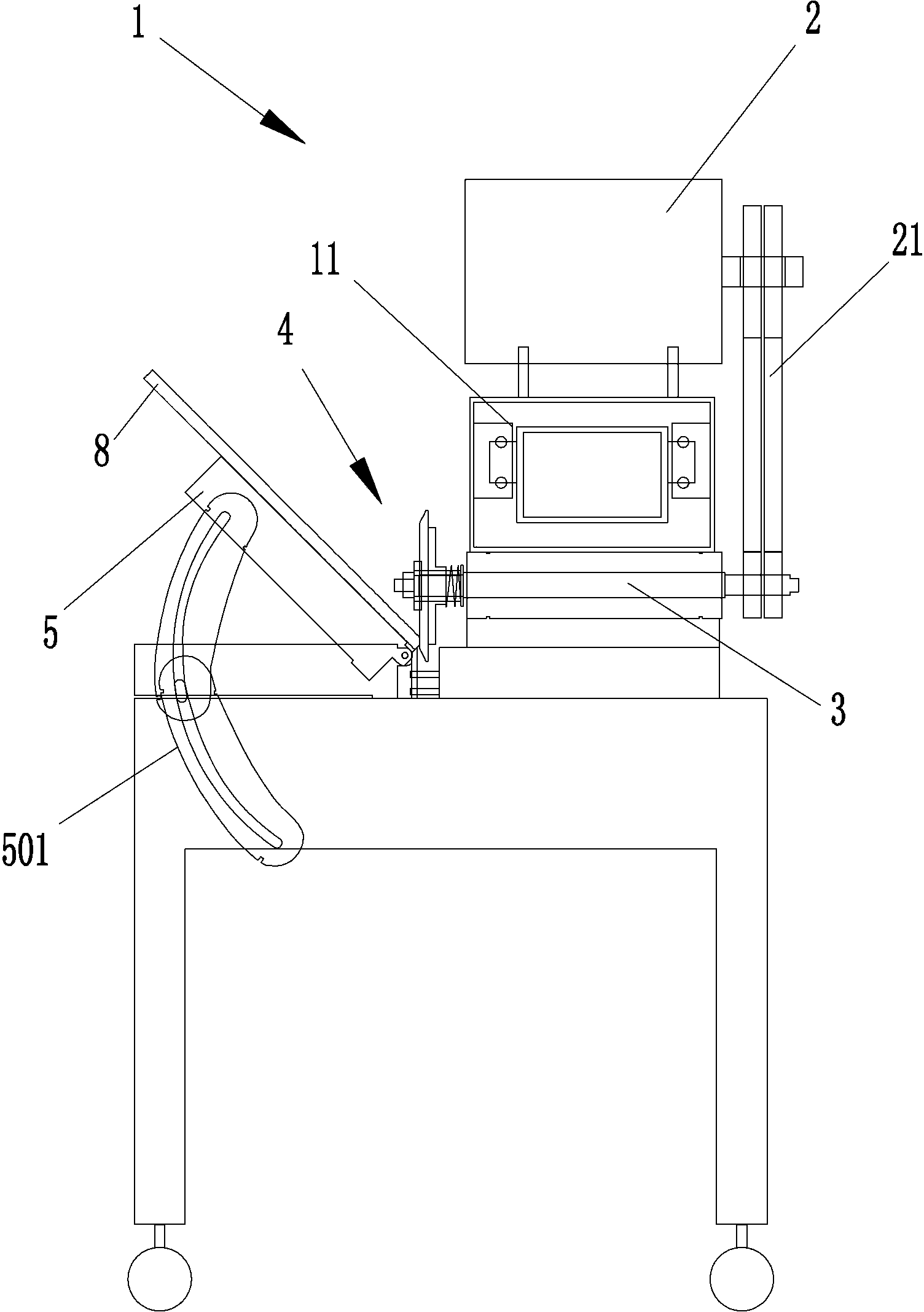
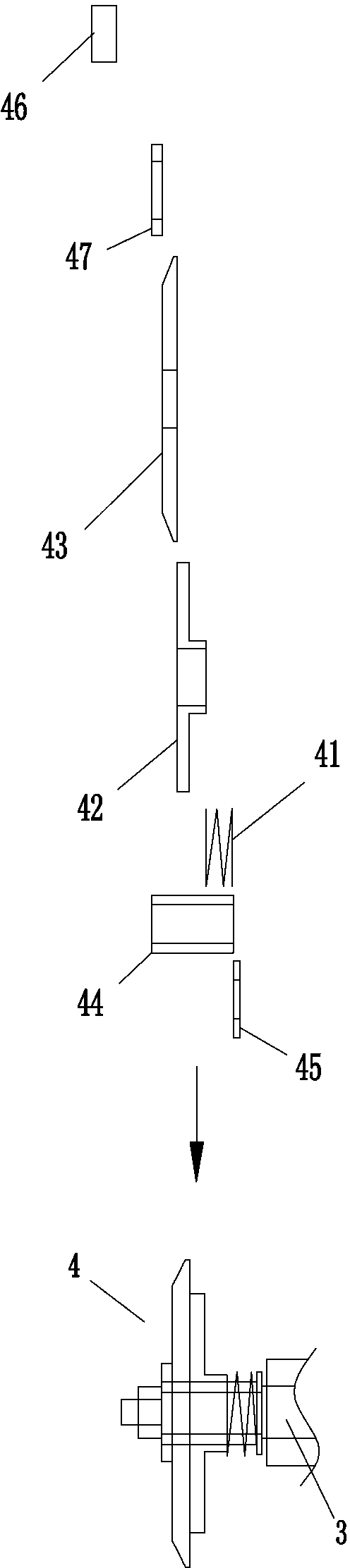
[0016] Embodiment 1: see attached figure 1 to attach figure 2 As shown, the polishing mechanism of the ceramic tile cutter with polishing function described in the present embodiment includes an organic case 1, a motor 2, a polishing shaft 3 and a polishing assembly 4, wherein a motor 2 is installed on the upper end of the case 1, and the polishing The shaft 3 is built in the lower end of the chassis 1, the motor 2 is connected to one end of the polishing shaft through a transmission belt 21, the other end of the polishing shaft 3 extends out of the chassis 1 and is matched with the polishing assembly 4, and the polishing assembly 4 includes a spring 41 , grinding disc suction cup 42, the water grinding disc 43 attached to the grinding disc sucker 42 disc surface, the suction cup chute ring 44 with multiple convex bodies 441, the pressure regulating plate 45, the limit nut 46 and the rubber ring 47, the described The side surface of the water grinding plate 43 is trapezoidal...

Embodiment 2

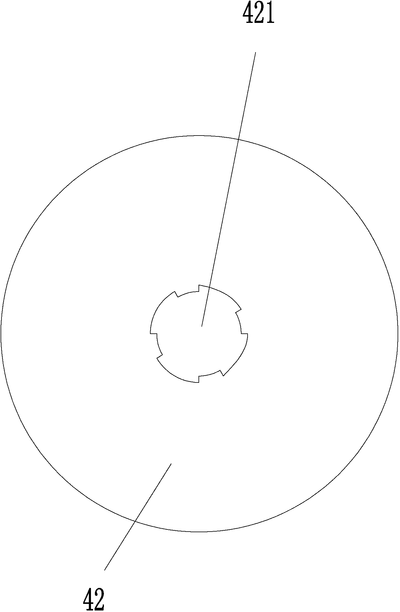
[0018] Embodiment 2: see attached image 3 to attach Figure 4 The difference between this embodiment and Embodiment 1 is that the protruding end surface of the polishing shaft 3 of the polishing mechanism has a plurality of convex strips 31 (or grooves) integrally formed, and the convex strips 31 and the disk surface are attached with a water abrasive sheet 43 The center of the grinding disc suction cup 42 is provided with a mounting hole 421 matched with the convex strip 31 (or groove). When the chamfer surface of the ceramic tile 8 to be polished contacts the water grinding disc 43, the grinding disc sucker 42 can extend along the polishing axis 3. When the outlet end moves horizontally on the surface, the spring 41 will shrink, thereby achieving the effect of automatic pressure regulation.


PUM


Abstract

The invention provides a polishing mechanism with a polishing function for a ceramic tile cutting machine. The polishing mechanism comprises a box. The upper end of the box is provided with a motor, a polishing shaft is arranged in the box, the motor is connected with one end of the polishing shaft through a transmission belt, and the other end of the polishing shaft extends out of the box to combine with a polishing component in a matched manner; the polishing component comprises an adjusting spring, a polishing disc sucker, a water polishing disc and a sucker sliding groove ring; the outer edge of the water polishing disc is a gradient oriented face, and the extending end of the polishing shaft is tightly sleeved with the sucker sliding groove ring; the adjusting spring and the polishing disc sucker sleeve the sucker sliding groove ring, and the end of the polishing shaft is tightly screwed to a limit nut and allows the sucker sliding groove ring to be constantly fixed between the limit nut and a pressure adjusting sheet; one side of the polishing component is provided with a feeding device with an adjustable angle. The polishing mechanism is simple in structure, handy and practical; the complex cylinder component design of a traditional cutting and polishing machine is abandoned, automatic pressure adjustment can be realized, polishing adjusting time is decreased, adjusting accuracy is improved, and producing efficiency and polishing quality can be improved effectively.

Description

technical field [0001] The invention relates to the technical field of a ceramic tile cutting machine, in particular to a polishing mechanism of a ceramic tile cutting machine with a polishing function. Background technique [0002] At present, most of the tile cutting machines have the function of cutting the vertical plane of the tile or chamfering the edge of the tile. Only a small number of tile cutting machines have the function of cutting the chamfered surface and polishing at the same time, but the polishing machine of the chamfering machine is usually Both use the piston rod cylinder to control the feeding and retracting of the polishing shaft with the polishing abrasive. The feeding and retracting of the polishing shaft will make the grinding wheel produce a greater impact when it touches the tiles. The cylinder controls the polishing shaft. The stroke and range of feeding and returning are relatively large, and the adjustment time is long, which reduces the product...

Claims


Application Information

Patent Timeline
IPC IPC(8): B24B9/06B24B29/02
CPCB24B9/06B24B27/06
Inventor 麦志辉
Owner 麦志辉
Why Eureka
Try Eureka