Continuous plasticizing production device and method

A production device and twisted cage technology, which is applied in the field of energy-saving and environmentally friendly continuous plasticizing production devices, can solve the problems of difficulty in fully recovering the performance of rubber powder, uneven electric heating temperature control, affecting the stability of the production process, etc. Small, improve plasticizing effect, reasonable structure design effect

Inactive Publication Date: 2014-04-30
张兴和
View PDF5 Cites 3 Cited by
  • Summary
  • Abstract
  • Description
  • Claims
  • Application Information

AI Technical Summary

Problems solved by technology

The problem with this process and equipment is that the rubber powder is cooled directly after the plasticization is completed. For the part of the rubber powder that is not sufficiently heated at high temperature, the direct cooling will have a certain impact on increasing swelling, softness and improving plasticity. , it is difficult to fully meet the requirements of recovering the properties of the rubber powder; the temperature control of the electric heating is not uniform enough, the heating of the rubber powder is not uniform enough, and the problems of coking, carbonization and plasticizing are prone to occur, which affects the stability of the production process; the equipment adopts screw stirring Drive, rubber powder is easy to adhere to the screw during high temperature plasticization, and it is not easy to remove
[0004] The Chinese invention patent discloses a production device and method of an environmentally friendly recovery rubber with the application number of 201010133770.5. The device uses a screw auger conveying with a certain gap between the mandrel and the mandrel to solve the problem of rubber powder sticking to the blade during the production and conveying process. question

Method used


Image

  • Continuous plasticizing production device and method
  • Continuous plasticizing production device and method
  • Continuous plasticizing production device and method

Examples


Embodiment Construction

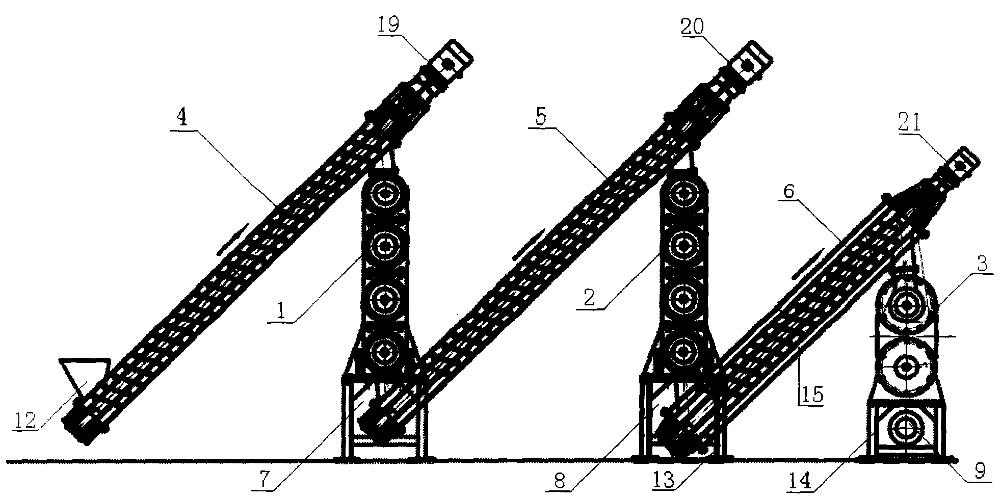
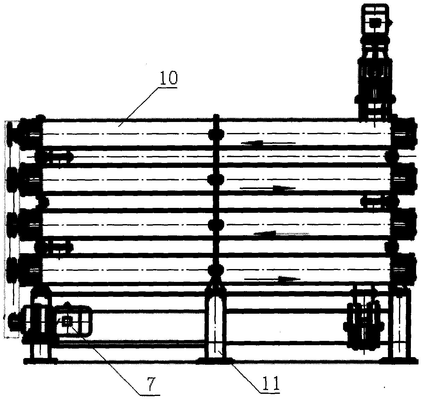
[0017] Such as figure 1 , 2 As shown, the continuous plasticizing production device is mainly composed of intermediate conveying cylinders 4, 5, 6, a set of heating and plasticizing twisted cages 1, a set of heat preservation twisted cages 2, a set of cooling twisted cages 3, electromagnetic induction heating 10 and the transmission mechanism 7, 8, 9, a set of heating and plasticizing twisted cages 1 provided in this embodiment is four heated and plasticized twisted cages A and B arranged in a row on the support 11 and connected to each other. . The inlet end of the heating and plasticizing cage A is connected to the outlet end of the intermediate conveying cylinder 4 arranged obliquely, and the inlet end of the intermediate conveying cylinder is connected to the feed hopper 12 . The outlet end of the heating and plasticizing twisted cage D is connected to the intermediate conveying cylinder 5 arranged obliquely, and the outlet end of the intermediate conveying cylinder 5 is...


PUM


Abstract

The invention relates to a continuous plasticizing production device. The continuous plasticizing production device is characterized in that a heat preserving and maintenance stranding cage set is arranged between a heating plasticizing stranding cage set and a cooling stranding cage set and communicated with the two sets; rubber powder conveying parts arranged in the heating plasticizing stranding cage set, the heat preserving and maintenance stranding cage set and the cooling stranding cage set are composed of rotating shafts and screw blades, wherein the screw blades are connected to the rotating shafts; and the screw blades and the rotating shafts are arranged at a certain spacing. According to the method, the plasticizing of the rubber powder is carried out in three process steps of heating, heat preserving and maintenance, and cooling. The method is characterized in that the rubber powder is uniformly heated, and the heated rubber powder is subjected to heat preserving and maintenance, thus the performance of reclaimed rubber can be recovered, and the plasticizing effect is greatly improved; the designed screw blades of the stranding cage enables sufficient agitating and conveying of the rubber powder in the heating, heat preserving, cooling and other working areas; and particularly the rubber powder is difficulty adhered to the rubber conveying parts.

Description

technical field [0001] The invention relates to a processing of waste rubber, in particular to an energy-saving and environment-friendly continuous plasticizing production device and method. Background technique [0002] At present, in the process of automatic and continuous production of waste rubber, the plasticizing process of the rubber powder mainly includes two process steps of heating and cooling. The heating part is to heat and plasticize the internal rubber powder of the auger or the drum through an electric heating device. , and continuously push the rubber powder forward through the screw rod during the plasticizing process, and send it to the next cooling equipment. The problem with this process and equipment is that the rubber powder is cooled directly after the plasticization is completed. For the part of the rubber powder that is not sufficiently heated at high temperature, the direct cooling will have a certain impact on increasing swelling, softness and impr...

Claims


Application Information

Patent Timeline
Patent Type & Authority Applications(China)
IPC IPC(8): B29B17/00
CPCY02W30/62
Inventor 张兴和
Owner 张兴和
Why Eureka
Try Eureka