
Intelligent RDF environment former

A forming machine and intelligent technology, applied in the direction of material forming presses, presses, manufacturing tools, etc., can solve the problems of reducing transmission efficiency, equipment debugging, overloading, etc., to achieve automation and intelligence, and improve work efficiency Effect

Inactive Publication Date: 2014-04-30
EGUARD NEW ENERGY AUTOMOBILE CO LTD
View PDF6 Cites 5 Cited by
  • Summary
  • Abstract
  • Description
  • Claims
  • Application Information

AI Technical Summary

Problems solved by technology

At present, most RDF ring die forming machines use traditional mechanical transmission, and their driving devices are generally composed of motors and V-belts. This transmission mode is difficult to adjust the equipment to a continuous and stable working state with high production efficiency. A piece of equipment needs Multi-person operation requires operators to keep an eye on the operation of the equipment at all times, which makes the operation difficult and the production efficiency is very low
When the existing mechanical molding machine performs normal RDF molding, the actual power used is only 60% of the rated power. It will also cause the motor to block, stop or even burn out, and the V-belt will slip and wear due to the blockage of the main shaft, which will reduce the transmission efficiency. Can't let the equipment play its due work efficiency
[0003] Chinese patent CN201140539Y discloses a ring die extrusion molding machine, which is equipped with an overload protection device, which is composed of a safety pin seat, a safety pin, etc., which can only play a protective role and cannot allow the equipment to exert its due working efficiency

Method used


Image

  • Intelligent RDF environment former
  • Intelligent RDF environment former
  • Intelligent RDF environment former

Examples


Embodiment Construction

[0035] Below in conjunction with accompanying drawing for further explanation:

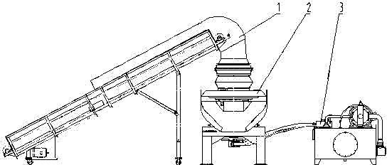
[0036] like figure 1 As shown, the intelligent RDF ring die forming machine described in the present invention adopts electromechanical-hydraulic integration technology. It is mainly composed of feeding device 1, forming host 2, hydraulic system 3 and electrical control system.

[0037] The feeding device 1 is composed of a feeding frame, a conveyor belt, a driving roller, a driven roller, a discharge hopper, a variable frequency motor and a reducer, and the speed of the variable frequency motor is controlled by a frequency converter.

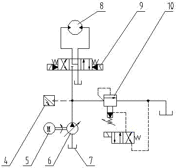
[0038] The forming main machine 2 is mainly composed of a feed hopper, a module fixing plate, a forming module, an extrusion wheel, a material copying device, a main shaft, a frame, etc. The main shaft is directly driven by a hydraulic motor, and the hydraulic system 3 controls the torque and torque of the hydraulic motor. Rotating speed.

[0039] like fig...


PUM


Abstract

The invention provides an intelligent RDF environment former which comprises a feeding device, a forming mainframe, a hydraulic system (3) and an electric control system. The feeding device comprises a feeding rack and a variable frequency motor, the forming mainframe comprises a spindle, a rack, a forming module and the like, the hydraulic system comprises a hydraulic motor, an electrohydraulic reversing valve, an overflow valve, a pressure transmitter, a motor, a constant-power variable pump, an oil tank and an oil pipe, and the electric control system comprises a PLC (programmable logic controller) and a frequency changer. Electric signals of pressure of the hydraulic system are monitored by the PLC through the pressure transmitter in real time, the spindle of the forming mainframe is controlled to rotate forwards and backwards or stop, and running of the variable frequency motor of the feeding device is controlled. Pressure signals reflecting load size are utilized to control related actions like automatic backward rotating, automatic forward rotating and stopping of the mainframe and enable feeding speed to be constantly matched with working speed of the mainframe, so that automation and intelligentization of equipment production can be realized.

Description

technical field [0001] The invention relates to a garbage disposal device, in particular to an RDF ring die forming machine. Background technique [0002] With the explosive growth of municipal solid waste, it is particularly important to recycle and reduce waste. The intelligent RDF ring die forming machine described in the present invention is to extrude the combustible substances after domestic waste has been processed by crushing, sorting, drying, etc., and then make it into solid fuel. Reserve, it can be stored at room temperature for 6-12 months without spoilage. At present, most RDF ring die forming machines use traditional mechanical transmission, and their driving devices are generally composed of motors and V-belts. This transmission mode is difficult to adjust the equipment to a continuous and stable working state with high production efficiency. A piece of equipment needs Multi-person operation requires operators to keep an eye on the operation of the equipment...

Claims


Application Information

Patent Timeline
IPC IPC(8): B30B11/22B30B15/26B30B15/30B30B15/16B30B15/22
CPCB30B11/201B30B11/005B30B15/308
Inventor 耿协义陈桦汤世民
Owner EGUARD NEW ENERGY AUTOMOBILE CO LTD
Learn More