Two-stage fuel reactor structure and technological process

A technology of fuel reactor and process flow, which is applied in the direction of granular/powdered fuel gasification, petroleum industry, and manufacture of combustible gas, etc. Problems such as residence time can be solved to achieve the effect of increasing the concentration and increasing the reduction reaction rate

Inactive Publication Date: 2014-04-30
SHANGHAI BOILER WORKS
View PDF5 Cites 4 Cited by
  • Summary
  • Abstract
  • Description
  • Claims
  • Application Information

AI Technical Summary

Problems solved by technology

The serial fluidized bed reactor is similar to the traditional circulating fluidized bed, consisting of a fast bed air reactor and a low speed bubbling bed / turbulent bed fuel reactor, with a flow sealing valve between the two reaction beds However, the simple low-velocity bubbling bed / turbulent bed structure is still difficult to meet the requirements of long residence time of particles; the double circulating fluidized bed reactor is composed of two circulating fluidized bed systems connected in series, which makes the system design and operation difficult. control has brought greater difficulties, and will also increase the system's economic investment

Method used


Image

  • Two-stage fuel reactor structure and technological process

Examples


Embodiment Construction

[0018] In order to make the present invention more comprehensible, a preferred embodiment is described in detail below with accompanying drawings.

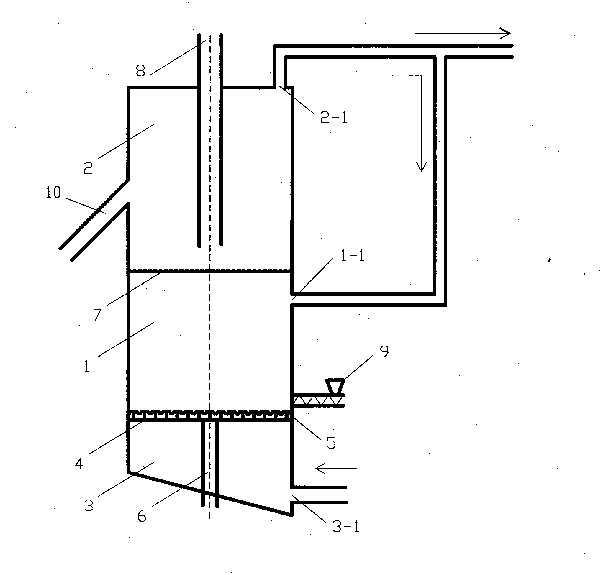
[0019] figure 1 Schematic diagram of the structure of the two-stage fuel reactor provided by the present invention, the structure of the two-stage fuel reactor consists of a gasification zone 1, a reduction zone 2, an air chamber 3, an air distribution plate 4, an air cap 5, and a slag discharge pipe 6 , grid net 7, feed pipe 8, screw feeder 9 and discharge pipe 10.

[0020] The internal space of the fuel reactor is divided into a lower gasification zone 1 and an upper reduction zone 2 by using a grid 7; an exhaust pipe is arranged at the upper end 2-1 of the reduction zone 2 to lead out the generated flue gas, and the exhaust pipe is provided with a tee. One of them is led back to the gasification zone gas inlet 1-1 as part of the gas supply to the reduction zone, and the other part is purified and condensed to obtain high-purit...


PUM


Abstract

The invention provides a two-stage fuel reactor structure. The two-stage fuel reactor structure comprises a fuel reactor cavity, wherein a grid net divides the fuel reactor cavity into a lower gasification zone and an upper reduction zone; a tee joint is arranged in an exhaust pipeline of an upper end of the reduction zone; one way of the tee joint is led back to a gas inlet of the gasification zone; an air distribution plate is arranged in the gasification zone; a hood is arranged on the air distribution plate; an air chamber is arranged below the air distribution plate; a slagging pipe passes through the air chamber to be connected with the lower end of the gasification zone; a screw feeder is connected with the side wall surface of the gasification zone; a feed pipe and a discharge pipe are arranged at the upper end and on the side of the reduction zone respectively. The invention also provides a technological process of the two-stage fuel reactor structure. The device provided by the invention has the beneficial effects that the gasification and oxygen carrier reduction processes of solid fuel are separated, so that the reduction reaction rate of the oxygen carrier is effectively increased and is matched with oxidation reaction of the oxygen carrier; the solid fuel is not in contact with the oxygen carrier, thus preventing the oxygen carrier from carrying ashes, unburnt carbon and other impurities, and simultaneously increasing the concentration of CO2 in the flue gas.

Description

technical field [0001] The invention relates to a two-stage fuel reactor structure and process flow, and belongs to the technical field of chemical looping combustion. Background technique [0002] Chemical looping combustion (Chemical looping combustion) technology is a revolutionary new combustion method, which decomposes the traditional one-step combustion reaction into two steps in the fuel reactor and the air reactor respectively, through the intermediate circulation of oxygen carrier (usually are metal oxides) supply oxygen from the air to the fuel. In traditional combustion reactions, because N 2 dilution, the CO in the flue gas 2 The concentration is only about 13%, and it takes a lot of energy to capture it; and in the chemical loop combustion process, the fuel and the air are isolated, so the flue gas generated in the fuel reactor will not be absorbed by the N in the air. 2 Diluted, its main component is CO 2 and H 2 O, high-purity CO can be obtained by simple...

Claims


Application Information

Patent Timeline
Patent Type & Authority Applications(China)
IPC IPC(8): C10J3/56C10J3/54C10J3/72
Inventor 熊杰倪建军李钰曾天成
Owner SHANGHAI BOILER WORKS
Why Eureka
Try Eureka