
Thermoelectric generation device for vehicle

A technology for thermoelectric power generation and vehicle use, which is applied to exhaust devices, noise reduction devices, combustion engines, etc., to achieve the effects of overcoming excessive volume, avoiding damage, and improving heat utilization efficiency

Active Publication Date: 2014-04-30
SHANGHAI INST OF CERAMIC CHEM & TECH CHINESE ACAD OF SCI
View PDF9 Cites 3 Cited by
  • Summary
  • Abstract
  • Description
  • Claims
  • Application Information

AI Technical Summary

Problems solved by technology

However, so far, there is no thermoelectric power generation device designed specifically for thermoelectric devices with this ring structure.

Method used


Image

  • Thermoelectric generation device for vehicle
  • Thermoelectric generation device for vehicle
  • Thermoelectric generation device for vehicle

Examples


Embodiment Construction

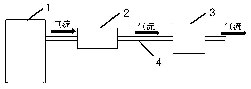
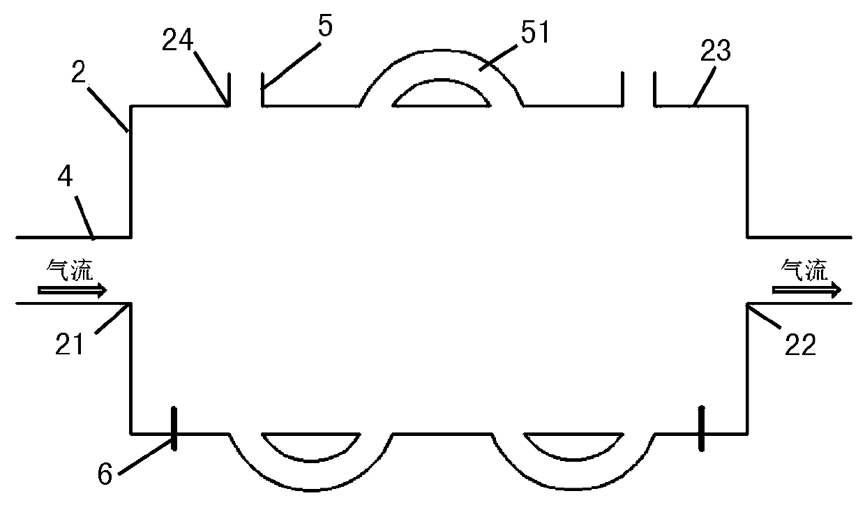
[0041] The vehicle thermoelectric power generation device of the present invention will be described in detail below with reference to the accompanying drawings and preferred embodiments. figure 2 It shows a schematic diagram of the external structure of a vehicle thermoelectric power generation device according to an embodiment of the present invention; image 3 show figure 2 The top view of the vehicle thermoelectric power generation device shown; Figure 4 show figure 2 A cross-sectional view along the horizontal direction of the vehicle thermoelectric power generation device shown; Figure 5 and Figure 6 show Figure 4 The partially enlarged schematic diagram of ; and Figure 7 show figure 2 A cross-sectional view along the vertical direction of the vehicle thermoelectric power generation device shown.

[0042] Such as Figure 2 to Figure 4 As shown, the vehicle thermoelectric power generation device of the present invention includes: a box body 2 arranged on ...


PUM


Abstract

The invention provides a thermoelectric generation device for a vehicle. The device comprises a box arranged on an exhaust pipeline of the vehicle, multiple hollow pipes arranged in the box in parallel, and a thermoelectric device arranged on the pipes in a sleeved mode and of an annular structure, wherein the box is provided with an air inlet and an air outlet, tail gas from an engine flows into the air inlet and is exhausted from the air outlet, and the distribution direction of the pipes is vertical to the airflow direction in the box. The thermoelectric generation device is simple in structure, compact in size and high in heat utilization rate, the structure of the bottom of the vehicle is kept as much as possible, and waste heat of the tail gas of the vehicle can be converted into electricity more effectively.

Description

technical field [0001] The invention belongs to the technical field of automobile manufacturing, and in particular relates to a thermoelectric power generation device for a vehicle, in particular to a thermoelectric power generation device which utilizes waste heat of exhaust gas from an automobile engine to generate electricity. Background technique [0002] As a new type of new energy and renewable clean energy technology, thermoelectric conversion technology has received extensive attention in the world in recent years. It uses semiconductor materials to directly convert heat energy and electric energy, and has the characteristics of small system size, high reliability, no emission of pollutants, and effective use of low-density energy. [0003] Among many thermoelectric materials, skutterudite-based compounds, as a typical medium-high temperature thermoelectric material, have great application prospects in high-tech fields such as the recovery and utilization of industri...

Claims


Application Information

Patent Timeline
Patent Type & Authority Applications(China)
IPC IPC(8): F01N5/02
CPCY02T10/12
Inventor 仇鹏飞陈立东黄向阳吴汀顾明夏绪贵
Owner SHANGHAI INST OF CERAMIC CHEM & TECH CHINESE ACAD OF SCI
Learn More