Controllable infrared photoelectric detection target device and diction method thereof

A technology for photoelectric detection and detection of targets, which is applied to devices using optical methods, weapon accessories, and ammunition tests, etc., can solve the problems of high power consumption, high cost, poor stability, etc., to improve efficiency and reduce energy consumption. , the effect of improving work efficiency

Active Publication Date: 2014-04-30
XIAN TECHNOLOGICAL UNIV
View PDF9 Cites 23 Cited by
  • Summary
  • Abstract
  • Description
  • Claims
  • Application Information

AI Technical Summary

Problems solved by technology

In order to improve the performance of the light curtain target, the patent CN101943549A proposed the design principle of using a line light source and a reflector to form a frame-type all-weather detection and speed measurement system. This method improves the sensitivity of the light curtain target, but due to the structure Limitation, the target surface is not large, and the reflective surface of the reflector is very flat. If there is a difference in the reflective material of the reflector, the reflected light will not easily fall on the photosensitive surface of the receiver.
In the patent CN202649229U, a laser reflection type large surface velocity measurement light curtain target was invented and designed. This light curtain target uses three optical lenses to splice the field of view and a 7-type array light source to form a detection light curtain, which is relatively expensive. Due to the large structure of the light source, the number of luminous tubes in the array is large, and the power consumption is as high as thousands of watts. In the continuous power supply system, the performance of some luminous tubes is different due to the jitter of the power supply during use, resulting in false triggering and stability. relatively poor

Method used


Image

  • Controllable infrared photoelectric detection target device and diction method thereof
  • Controllable infrared photoelectric detection target device and diction method thereof
  • Controllable infrared photoelectric detection target device and diction method thereof

Examples


Embodiment 1

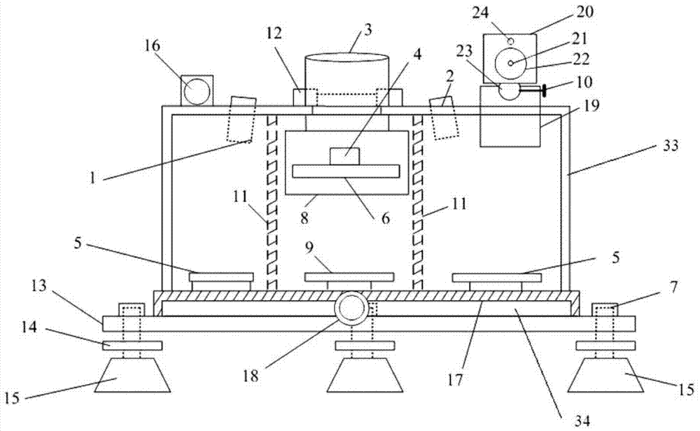
[0028] Such as figure 1 as shown, figure 1 A controllable infrared photoelectric detection target device is shown, which includes a triangular base 13, at the three corners of the triangular base 13, three high and low level knobs 14 that can adjust the height of the triangular base 13 are respectively connected with Three feet 15 are connected and fixed horizontally on the ground or on the test bench through the three feet 15, wherein the triangular base 13 and the corresponding high and low level knob 14 and the feet 15 are connected by studs 7 Connected together, the upper surface of the triangular base 13 is fixedly connected with the connecting raised disk 34, for example, a welding connection method can be used, and a circular base 17 is nested and connected on the connecting raised disk 34. The base 17 can rotate relative to the connecting raised disc 34, so that the detection target device can freely rotate on the triangular base 13. In addition, a nesting position be...

Embodiment 2

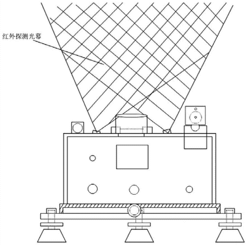
[0044] see figure 2, using the controllable infrared photoelectric detection target device in the above-mentioned embodiment 1 to form a parallel light curtain velocity measuring system. Wherein, in the step of carrying out the infrared photoelectric detection method according to the test system in Embodiment 1, the muzzle flare trigger 20 of the second controllable infrared photoelectric detection target device is not adjusted, and the first controllable infrared photoelectric detection target device is used to control the second controllable infrared photoelectric detection target device. The first controllable infrared photoelectric detection target device and the second controllable infrared photoelectric detection target device are in the form of four line infrared light-emitting lasers. Because the distance between the first controllable infrared photoelectric detection target device and the second controllable infrared photoelectric detection target device and the timi...

Embodiment 3

[0046] see Figure 6 , using the photoelectric detection target in the above-mentioned embodiment 1 as the synchronous trigger start signal of the intersection vertical target coordinate test system. The intersecting vertical target coordinate test system uses two linear array CCD cameras to merge into a detection surface, and uses the principle of binocular vision to realize the coordinate position measurement of the target passing through the detection surface. Since the linear array CCD camera works in a continuous acquisition mode, during the test , if the continuous acquisition method is adopted, the amount of data will be large, which will cause the processing speed of the computer to be too slow and affect the system work, and even cause the computer to crash or the camera to continuously acquire overheating and cannot work normally. To affect the test work, a single real-time trigger working method can be adopted. In order to provide synchronous acquisition signals und...


PUM


Abstract

The invention relates to a controllable infrared photoelectric detection target device. The controllable infrared photoelectric detection target device comprises a round bottom seat and a target housing which is fixed on the round bottom seat, wherein a laser emission unit, an energy collection unit, a control circuit unit and a signal trigger unit are arranged in the target housing. Additionally, the controllable infrared photoelectric detection target device further comprises a horizontal adjustment unit. According to the controllable infrared photoelectric detection target device, a double high power infrared emission laser device is used to form a fan-shaped detection light curtain, the detection light curtain is controlled by using an external triggering mode, measurement of speed and position coordinates of all-weather large target area pellets of a field trajectory can be achieved, and simultaneously energy consumption is reduced, and work efficiency of equipment is improved.

Description

technical field [0001] The invention relates to a detection device for detecting projectile parameters and a corresponding detection method. Specifically, the invention relates to a controllable infrared photoelectric detection target device and a corresponding detection method. Background technique [0002] In the field of shooting range testing, the velocity of the projectile and the measurement of the coordinates of the target stand have always been the core test parameters for the development of guns, cannons, bullets, etc., which restrict the development of weapons and ammunition. The test equipment includes coil target, sky curtain target, light curtain target, laser target, etc. The sky curtain target is widely used in the shooting range due to its small size, light weight, simple operation and reliable performance. However, since the sky curtain target uses a visible light detector as The detection principle of the core unit is greatly affected by the natural environ...

Claims


Application Information

Patent Timeline
Patent Type & Authority Applications(China)
IPC IPC(8): F42B35/02G01P3/36
Inventor 李翰山雷志勇卢莉萍高俊钗宋春焕
Owner XIAN TECHNOLOGICAL UNIV
Why Eureka
Try Eureka